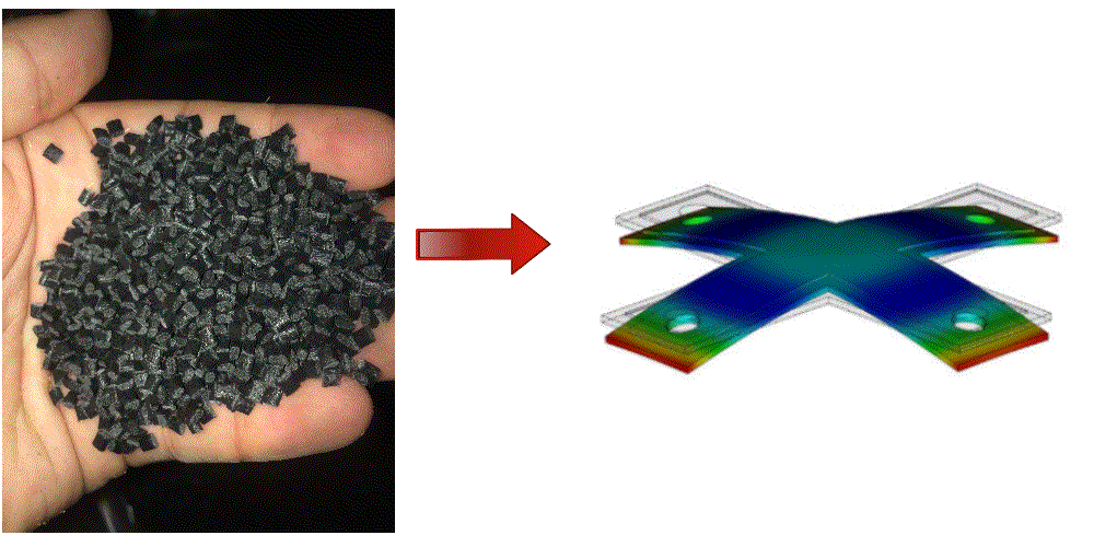


For Plastics Injection Molding, the addition of glass or carbon fiber into a polymer is initiated to typically strengthen and increase stiffness in a part. There are significant factors that must be considered when fiber is added that will have an impact on part quality and deflection.
These include:
- Material viscosity
- Material type (i.e. crystalline, amorphous or semi-crystalline)
- Part design
- Process conditions (filling rates, melt and mold temperatures and pack pressure).
Adding fiber to a material is not so simple. It is very important to understand the characteristics and behaviors of that material and adding fiber will dramatically influence these factors. Fiber has orientation characteristics which will impact the performance of the part. Having the material tested or acquiring the test data will provide a better understanding of how the material will perform.
Why is fiber orientation important? Orientation of the fiber can provide increased properties when it is highly and consistently oriented, which is typically in the direction of flow. Conversely, the properties are at a much lower transverse to the direction of flow. Similarly, the shrinkage characteristics are also impacted by fiber orientation. The polymer will shrink less in the direction of flow (parallel) and more transverse (perpendicular) to flow. This variation will cause a part to warp. Below is an image showing the shrinkage properties of a 30% glass filled polypropylene.

Notice that the observed nominal shrinkage in the direction parallel to flow was 0.1530% and 0.7741% in the direction perpendicular to the direction of flow. That’s 5 times more shrinkage in the direction perpendicular to flow. This variation within the part is what causes part warpage and deflection.
In order to have a better understanding of the factors that impact fiber distribution, we will discuss how fiber orients within the cross-section of a part.
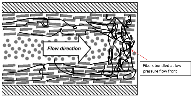
Fiber orientation within the part cross-section is critical with regards to consistent and uniform (isotropic) properties within the part. The use of fiber will offer the greatest strength if the fiber is oriented uniformly within the entire part. However, with regards to the flow characteristics of a polymer within the geometry of the part, there are many regions where the flow patterns cause the fiber to be less oriented or more random. These regions will have less strength. Furthermore, weld lines within the part will be very weak. A weld line that forms and does not continue to be pushed, yet flows, downstream will also be weaker than a weld line that does get pushed downstream. When a weld line forms, it will have a considerable amount of fiber at the head of each flow front that will abut against each other and not mix. This is due to the lower density glass fiber migrating to the head of the flow creating a ‘bundle’ of fiber that meets at the weld line location. This bundle of fiber displaces the polymer yielding a weld line with very poor mechanical strength. Without the necessary polymer molecule to intertwine, the resulting weld line is prone to being weaker than the same resin without glass fiber. If the weld line initially forms then gets pushed further downstream, the glass fibers will then get dispersed creating a higher strength zone. Below is an image showing the orientation at the weld line locations. Notice how the simulation result shows the fibers are randomly oriented at the weld line locations (blue lines).

The viscosity of the material can have a large influence on the behavior of glass fiber distribution. As mentioned previously, due to the inherent density variation between the fiber and the polymer, the glass fiber has the tendency to be pushed to the head of the flow front due to the pressure gradient within the polymer. A lower viscosity material such as a PA6/6, as compared to polycarbonate, will allow the glass fiber to move more readily within the polymer and migrate to the head of the flow front quicker and easier. This is commonly seen in round parts such as gears with spokes where the flow front will propagate outward in the spokes and as the flow front meets around the perimeter of the part, the glass fiber is abundant and the weld lines that form are poor due the lack of base resin coupled with the high content of randomly oriented fiber.
The filling rate can have a significant impact on glass fiber orientation. When the filling rate is increased, the fibers will have a higher degree of orientation within the part cross-section. If the filling rate is too fast, the stress on the fibers can cause the fibers to break therefore decreasing the strength of the overall part.
The cross section is also critical with regards to fiber orientation. If the part cross-section decreases then the velocity profile will increase and therefore create a higher degree of glass alignment in that region. If the cross section increases then the velocity will decrease and there will be a higher degree of random orientation as seen below.

The nature of the polymer and how it shrinks will depend on the 2nd stage of the molding cycle, pack stage.
The pack stage is important because we want to minimize the shrinkage effects of the polymer on the deflection of the part. Remember that the shrinkage of a fiber filled polymer is greater in the transverse direction of flow. The shrinkage can be kept to a minimum by ensuring enough pack pressure is used, providing enough pack time.
Since material shrink is critical, the type of polymer will also have an impact when using fiber. A crystalline material will shrink more than a semi-crystalline material, which will shrink more than an amorphous material. The shrinkage characteristics of each type of material will have an impact with regards to fiber orientation.
While the incorporation of fiber into a polymer can generally improve part properties, it can also cause potential issues such as weak weld lines and undesirable part deflection. Material type, viscosity, part design and processing can all contribute to the outcome of the quality of the part when using fiber fillers. Understanding the combined factors’ influence on the part is challenging. It is highly recommended that a flow analysis be conducted in order to identify how these factors it will affect the part you are creating.
Contact Bozilla Corporation today and let’s discuss how we can successfully contribute to your project. Bozilla Corporation’s Injection molding Team has over 20 years of experience analytically and on the floor. We specialize in optimization, consulting, engineering, troubleshooting and Autodesk Moldflow software training. Additionally, our plastics engineers have a full understanding of polymers and how they influence an injection molded part. Your success is our success. Our skilled Team is focused upon meeting the goals and timelines of our customers.
www.BozillaCorp.com, 800-942-0742, info@BozillaCorp.com
About Bozilla Corporation: https://youtu.be/HIUfzwf1x90
About the Author:
Chris Czeczuga is a Plastics Engineer, Injection molding expert, Military Veteran and the President of Bozilla Corporation. He has proven success with many Fortune 500 companies throughout the injection molding industry. A graduate from UMass Lowell, he is Expert Certified with Autodesk, has 20+ years of field experience, intimate knowledge of injection molding part, tool and feed system design. Bozilla Corporation’s success is built on providing the highest level of injection molding simulation and consulting advice to businesses who have short lead times, require an efficient, cost-effective molding process, and desire to produce a correct part the first time.