Failure Diagnosis for Injection molding

Bozilla Corporation’s core business is performing CAE analyses, specifically mold flow analyses, on products to optimize both design and process . Our procedures and standards set a benchmark to create the highest degree of part quality with the least amount of difficulty and waste.

Because many companies have not used FEA, they are turning to the injection molding specialists at Bozilla Corp with issues relating to part failure or processing problems. Fortunately, we are solving many of them with Failure Diagnosis.

What exactly is Failure Diagnosis?

Failure Diagnosis is the process of identifying why a product or process isn’t performing properly.

The injection molding professionals at Bozilla Corporation have cultivated and executed proven techniques to execute this vital task and resolve our customers’ concerns on all levels.

This type of diagnosis requires calculated procedures and thorough knowledge in:

✔ CAE Analysis

✔ Root Cause Analysis

✔ Experience with similar products/issues

✔ Indepth knowledge of polymers

If you are experiencing problems with a product in the field or with its process, we will implement our procedures to assist in solving these issues.

 Some examples may include:

➤ Start up times for a tool are taking longer than expected, the process is difficult to stabilize, or the start up time on the same tool varies from machine to machine

➤ The process has variation and too many bad parts are being produced

➤ The parts seem to be fine but are failing in the field which causes customer dissatisfaction and more work/costs for you

As an added bonus, the Failure Diagnosis procedures can further lean your process and potentially save you money.

Bozilla Corporation has worked extensively with companies to resolve their injection molding performance issues. Contact us today and find out how we can help diagnosis any issues you may be having with your injection molding product and/or process and get you back on track!


www.BozillaCorp.com

We Know Injection Molding! Plastics Engineering, Consulting, Optimization, Failure Diagnosis, Training

About the author

Chris Czeczuga is a Plastics Engineer, Injection molding expert, Military Veteran and the President of Bozilla Corporation. He has proven success with many OEM’s Tier 1’s, Tier 2’s, Tool Shops, Molding shops, Part Designers, Processors and Fortune 500 companies throughout the injection molding industry. A graduate from UMass Lowell, he is Expert Certified with Autodesk, has 20+ years of field experience, intimate knowledge of injection molding part, tool and feed system design. Bozilla Corporation’s success is built on providing the highest level of injection molding simulation and consulting advice to businesses who have short lead times, require an efficient, cost-effective molding process, and desire to produce a correct part before mold steel is cut.

FEA analysis experts

In this economic climate, it is critical to create higher quality processes and parts while keeping costs as low as possible. This typically means getting analysts involved in the beginning phases of a project. Because a mold typically costs in the range of $12,000 to above $200,000, spending less money up front with analytical work will save you from costly tool re-work at the end of a project.

More businesses are turning to mold flow analysts to provide in-depth, technical knowledge before, during, and after the course of their project. Whether the analyst is internal or is a hired consultant, it is extremely important to know what type of experience and knowledge they have in order to take full advantage of their expertise.

What basic requirements should an Injection mold flow analyst (example: Autodesk Moldflow) have when analyzing the injection molding process.

Qualities of an injection molding analyst

  1. Injection molding knowledge: What type of focus does your analyst have in the injection molding sector? For instance, are they knowledgeable about mold design, polymers, and flow, etc?

Having an analyst that fully understands the scope of their position is an absolute necessity. In order to have a comprehensive understanding of their job, analysts must be knowledgeable in all aspects of the injection molding process. This includes injection molding processing, mold design, part design, and polymer chemistry and properties(e.g. a plastics engineer).

Plastics engineer

Plastics Knowledge: Is the analyst a Plastics Engineer or will a Plastics Engineer be involved?

Without a full understanding of polymers, it is extremely difficult to understand polymer behavior during processing. This understanding begins at a molecular level and extends far beyond standard processing knowledge.  A Plastics Engineer is able to identify the differences between polymers and each polymer’s flow characteristics. This information can be used in conjunction with the simulation software to optimize the analyzation process. Therefore, it is crucial to have a Plastics Engineer involved with plastics processing.

injection molding worker

Injection Molding Experience: Has the analyst ever run an injection molding machine or been formally trained on one?  Does he/she understand ancillary equipment such as thermolators/chillers?

Without injection molding experience, it is difficult to properly analyze such a process.

A mold flow analyst is typically required to identify and understand polymer flow behaviors within the injection mold. Frequently, this can involve analyzing the 1st stage, 2nd stage, and cooling stages of the injection molding process. If your analyst must survey these phases of the injection molding process, it is extremely important that they have a FULL understanding of what is occurring during the injection molding process. e.g. Is the process de-coupled? Does the injection molding machine use accumulators? does the injection molding analyst understand what screw bounce is? Platen deflection? Cantilevering the tool? etc.

injection mold

Mold Design

A flow analyst is sometimes required to make design recommendations or changes to a mold to further optimize a process. In order to understand how to suggest making such changes, it is vital that they are educated in mold manufacturing and design.

Sometimes a change cannot be made due to cooling line or ejector pin interference. Perhaps there is ‘action’ (e.g. slides, etc.) within the tool that would prohibit such changes. There are many other examples that could be cited, but the point has been made. This understanding of mold and tool design is critical in order to properly optimize a mold.

Analysts are becoming more integral in the injection molding process. It is imperative to be informed about the knowledge and experience your analyst is bringing to the table. Furthermore, it is essential to know if they have a formal understanding of injection molding processing, mold design, part design, and knowledge of polymers/plastics. Formal training and floor experience are critical. The more skills and knowledge your analyst brings to the project the more successful your project will be.

Bozilla Corporation- We Know Injection Molding! Plastics Engineering, Consulting, Optimization, Failure Diagnosis, Training

Chris Czeczuga President Bozilla Corporation

About the author

Chris Czeczuga is a Plastics Engineer, Injection molding expert, Military Veteran and the President of Bozilla Corporation. He has proven success with many OEM’s Tier 1’s, Tier 2’s, Tool Shops, Molding shops, Part Designers, Processors and Fortune 500 companies throughout the injection molding industry. A graduate from UMass Lowell, he is Expert Certified with Autodesk, has 20+ years of field experience, intimate knowledge of injection molding part, tool and feed system design. Bozilla Corporation’s success is built on providing the highest level of injection molding simulation and consulting advice to businesses who have short lead times, require an efficient, cost-effective molding process, and desire to produce a correct part before mold steel is cut.


Console Fill

In this discussion, we will explore a part that was injection molded and scanned for deflection. Interestingly, the actual deflection did not match that of the analyzed part. Unfortunately, this can sometimes happen and when it does, it is the responsibility of the software expert to investigate why the predicted analysis results are not matching the floor results. This can be a challenging task.

In the engineering world, it is common to hear the phrase ‘garbage in equals garbage out’. In other words that phrase means that all inputs plugged into any set of calculations will directly influence the outcome of those calculations. When it comes to FEA, having correct input data is especially critical since technical software can only be as good as what is entered into each specific section. But what steps should be taken if you have ensured that the analysis is set up correctly yet, the analytical results do not match the results on the floor? In the sample study below, we will take a closer look.
For this study, we will look at a part that we will call the ‘console’:

Console Fill Console DeflectionConsole


We will compare the analytical inputs to the inputs used on the floor. Then, we will explore how the analytical results compare to those on the floor.

In preparation for any analysis, the user must take the necessary precautions to ensure that the inputs in the mold filling software are as accurate as possible.

Part model

1) Is the part model prepared so that it meets or exceeds the standards that the software supplier recommends?

Yes, the part was modeled as a 3D model and exceeds the recommended criteria.

Feed system design

2) Does the feed system match the final design of the finished product?

Yes, it was designed per the specifications provided by the tool shop.

Material data

3) Is the material data in the analysis the same as what is being used on the floor?

Yes

   Is the material card comprehensive i.e., is it fully characterized?

Yes

Process inputs

4) Do the process inputs in the software match the floor inputs?

Yes, see the Table 1. Below

analytical process setting vs. floor process setting


Once the inputs have been confirmed as optimal and correct, we inspect the results and compare them.

First, we examine the filling pattern to see if it is predicted correctly.
To determine the correlation of flow patterns between Moldflow and the floor, a short shot study was conducted.

The Moldflow process was loaded into the injection molding machine to see if the floor could replicate the Moldflow process.

NOTE: The part data in Moldflow did not include the shelf where the hot drop was located on the part.

The images below show how the short shots on the left very closely match the predicted flow pattern on the right.

Actual short shot vs. Analytical short shot

actual short shot vs analytical short shot


Actual short shot progression vs. Analytical short shot progression

actual short shot progression vs. analytical short shot progression


The pictures below indicate the analysis is predicting flow patterns accurately. However, in both cases (floor and analysis) the part is filling in an imbalanced fashion (the bottom of the part is filling before the top).

Actual short shot near end of fill

actual short shot near end of fill


Analytical short shot near end of fill

analytical short shot near end of fill


Having confirmed the processes and the filling patterns match, we will now consider the measured deflection.

This image shows the actual measured deflection of the Console, via scan:

scanned part deflection


The green image below shows the analytical results utilizing the surrogate material overlaid with the scanned floor data, in blue.

Moldflow is predicting the correct downward trend on the top of the part with a 6.49mm variation (underprediction) from the scanned in part. For the sides of the part, Moldflow is also predicting the correct outboard trend with a 6.26mm variation (underprediction). On the bottom of the part, Moldflow is correctly predicting the trend and the magnitude of deflection with a 0.0mm variation.

Overlay analytical part deflection vs. Scanned part deflection
(Actual material)

overlay analytical part deflection vs. scanned part deflection


Noticing that the deflection prediction does not match the floor, we must consider all potential variables. Some of those variables are the available technologies in the software, Midplane, Dual Domain, 3D, BEM Cooling, FEM Cooling, the list goes on. This is where it is important to have a user who has an extensive and enduring understanding of the software in addition to having a good relationship with the software company. This unique collaboration of experienced FEA software experts yields a clear understanding of which technology will work best for the part design.

As part of our due diligence, we also tested each technology in the software and found that the 3D with BEM Cooling had the closest prediction.

For this example, the 3D with BEM Cooling technology was used.

Digging Deeper
Now that we checked all the inputs along with the process, we need to take an even closer look and dig deeper into some of the data that we have less control over, such as the material data.

The material data is a Moldflow .udb file supplied by the material supplier. Upon inspection, all the data fields are populated and none of the data is surrogate.

However, the quality indicators were not populated which raised a flag.

To explain, whenever a material data file is created by a certified Autodesk provider, the quality fields will be populated. Noticing they are not populated raises suspicion about the quality of the remaining data in this material card.

We now had to determine if this material card was valid. To make this determination, we ran the comparison analysis utilizing a material card that we knew was trustworthy and would provide accurate results. We selected a comparable material based on the rheology, thermal and mechanical properties. We utilized the same process settings as previously run with the original material card.

After the comparative analysis was complete, we compared the deflection results with that of the floor. We found that the prediction was not exact, but much more accurate.

The green image below shows the analytical results utilizing the surrogate material overlaid with the scanned floor data, in red. As shown, the predicted results are much closer to reality.

Moldflow is predicting the correct downward trend on the top of the part with a 3.77mm variation (underprediction) from the scanned in part. For the sides of the part, Moldflow is also predicting the correct outboard trend with a 1.88mm variation (underprediction). On the bottom of the part, Moldflow is correctly predicting the trend and the magnitude of deflection with a 0.0mm variation.


Overlay analytical part deflection vs. Scanned part deflection
(Surrogate material)

overlay analytical part deflection vs. scanned part deflection -surrogate material


The analysis with the surrogate material provides results which are closer to that of what is being seen on the floor, about twice (or greater) as accurate as the original material card. Since the material is not the exact grade, we cannot expect it to match up perfectly.   However, we now see the influence of the data within the material card on the accuracy of the predictions.  If the material data card had correct and trustworthy data, we would be very confident that the results would be almost identical to those on the floor.

In summary, we have looked at a part that was injection molded, scanned for deflection, and compared it to that of the analyzed part. We found that when all process conditions were matched, the predictive deflection results were much greater than that of the actual part.

After a thorough investigation it was found that the material data input (material card) was in question. A quick test was performed with the same analysis utilizing a trustworthy material card which proved to be a more accurate prediction.

It is critical to ensure that all inputs of an analysis are vetted so the precision level of the results are as high as possible. A competent and skilled FEA professional will be able to identify and address any technical issues that may arise to ensure your project results reflect the highest degree of accuracy.

Contact Bozilla Corporation today to discuss how our injection molding experts can assist you in manufacturing a successful tool!

Finite Element Analysis (FEA) has been available to the injection molding industry since approximately 1978 when Moldflow pty. Ltd produced the first simulation software to be used to optimize all phases of design and production processes for injection molded plastic parts.

Over the years, FEA has proven to be a successful, cost-saving optimization method used for injection molded tool manufacturing.


injection molding trouble shooting

Prior to FEA, a typical method used to refine product and process was to cut tool steel and design a feed system based on experience with older, comparable tools. This method is also known as the trial and error method.

This type of “guessing” process has cost manufacturers thousands of dollars in re-tooling and time delays that could have been prevented if they had first utilized FEA to troubleshoot the product and process.

The question remains, “Should FEA be used for every tool?”  The answer is YES! Whether it is a new tool replacing an old tool running the same part, a New Tool being built for a new part, or a new mold for an existing part, FEA can positively refine both the quality of mold and the process.

FEA is a gift to plastics manufacturers in that it provides an inside look at both the product and process before any steel is cut or altered.  The refinement of product and process allows the manufacturer to perfect their part and save both time and money by limiting or preventing future rework.

Contact Bozilla Corporation to assist you in achieving a successful part based on your budget and timing goals for your next project.  We will provide you with detailed project data empowering you to make the most informed decisions to create a high quality mold.

Do you remember the cost of your last mold?  If the answer is “yes”, do you really want to pay for it again because of rework/redesign?  

The plastic injection molding experts at Bozilla Corporation have over 20 years of experience with Autodesk Moldflow software, feed system design and field experience. We provide the highest degree of professionalism, knowledge and quality to every project.  Contact Bozilla Corporation Today and Let’s get started!

Conformal cooling has become the latest trend in the injection molding industry.   As it compares to traditional gun-drilled cooling lines, it appears to be better, but is that always the case?  We will discuss the comparisons and application of both traditional cooling versus conformal cooling as it applies to heat removal of the polymer/part.

When designing cooling for injection molds, several factors must be understood with regards to the properties of the tool steel such as the type of steel and its corresponding properties i.e.  thermal conductivity, thermal diffusivity, specific heat capacity and density.   Those same properties must be considered for the coolant along with Reynolds number and flow rate.

Thermal conductivity:

A measure of a materials ability to conduct heat as shown below:

Thermal Conductivity

Thermal diffusivity:

The thermal conductivity divided by the density and specific heat capacity (at constant pressure) as shown below:

Thermal diffusivity

In order to take advantage of these properties, certain guidelines should be considered such as the spacing between adjacent cooling circuits, thickness or cross section of the circuits and the spacing between cooling circuits and the cavity.  The flow rate must be sufficient enough such that the coolant is turbulent (Reynolds number above 8000) in all regions of the circuits in order to have maximum heat removal.

Conventional Cooling (gun-drilling):

Gun drilled cooling channels are straight holes cut through the tool steel.  Because these are straight holes, it limits the regions in which holes can be cut such as in any action within the tool or small or difficult regions near the cavity of the tool.  Implements can be used such as heat pipes (thermal pins), bubblers, baffles and small circuits and high heat-transfer materials.  However, there are still regions within the tool that are difficult to implement cooling and these regions are typically accepted.  They can cause issues within the mold such as parts sticking or controlling cycle time.

Gun drilled cooling channels are very adequate when sized and spaced correctly.  Basic guidelines will take advantage of the properties of both the coolant and the cooling channels:

  • The spacing of the cooling channel from center-line to center-line (pitch) should be no more than 3 times the diameter (3D).
  • The distance from the cooling channel to the cavity surfaces should be no more than 1.5 times the diameter (1.5D).

If these simple guidelines are maintained, there will be adequate cooling for the cavity as long as the coolant is turbulent through the channels.

Unfortunately, not every tool design is simple enough for gun drilling to address the cooling needs of the tool.  Therefore, we must also consider the application of conformal cooling.

Conformal Cooling:

The principle of conformal cooling is within the title itself, for the cooling to conform to the surface of the cavity.  It should conform to the surface wherever it is intended whether it be on the cavity or core side of the tool or within an insert or any action within the tool.  Conformal cooling should address any cooling needs within the tool in order to prevent any latent heat or hot spots in the tool therefore maximizing cooling efficiency and minimizing cycle times.

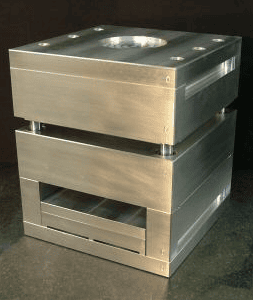
Conformal cooling can exist as a small circuit routed exactly where coolant is desired such as with an insert for a part shown in the example below:

Conformal cooling circuit

Conformal cooling can also be a fully jacketed cooling circuit encompassing the entire outer surface of the cavity as shown in the example below:

Conformal cooling jacketed

The idea of conformal cooling is simple, however, the design is a more complicated issue.

It is imperative that the design allow for adequate flow ensuring turbulence throughout the coolant jacket and preventing any dead spots.

In the images below the velocity of the coolant is displayed on a color band where blue is a zero velocity and red is a maximum of 50 inches per second.  In this mock-up design, the image shows how the coolant has dead spots (zero velocity) between the entrance locations then disperses from the entrances and slowly increases in velocity across the jacket until it reaches the exit where it reaches maximum velocity again.  This is a great example of how the analysis can reveal the impacts of design on cooling efficiency.

Cavity side:

Cavity Side

Core side:

Core Side

The image below shows the comparison of traditional cooling with conformal cooling and how it relates to the mold surface temperature with the cooling rate of the part.

Cooling comparison

The top row shows the temperature of the tool steel as represented on the part.  The bottom row shows a blue color which is representative of any material with a residual temperature above the transition temperature (ttrans), temperature at which the polymer goes from the molten to the solid state, in this case 258.8F and transparent if it is cooler than the ttrans.

When comparing the bottom residual temperature with the above mold surface temperature at the same point in time within the cycle it can be seen that:

  • The traditional cooling has a little of the perimeter which is below the ttrans but a consistent thin layer across the part which is still above ttrans.
  • The conformal cooling is cooled a little further (shown as speckled regions that are below ttrans) and has more consistent cooling trends across the lifter regions since there is cooling in them. Even with low velocities in the cooling jacket, the cooling remains slightly improved over traditional cooling.  However, it is always recommended to have turbulent flow throughout all regions of the cooling jacket.

The top row of mold temperature plots shows a significant amount of improved cooling.  However, the below row of part temperature plots shows a small amount of temperature improvement.  This trend suggests that improved tool cooling (conformal cooling) has an impact but it is a relatively small impact on heat removal in the part, approximated at 5-10% improvement.

The explanation for this:  The plastic creates a frozen layer on the wall of the mold which becomes a thermal barrier for the molten inner layers and based on the thermal characteristics of the polymer, heat will only leave the polymer as fast as is thermal properties will allow making the polymer the limiting factor with regards to heat removal.

Part Cooling

When properly designed, conformal cooling can maximize the cooling efficiency of a tool, but it is critical to understand that the limiting factor is what you are trying to cool.  The thermal properties of the polymer control the cooling rate of the part itself.

The below images show how the part freezes from the mold surface inward to the centerline of the part.

Percent Frozen @ 2.46 seconds into the cycle

2.46s part freeze

Percent Frozen @ 4.83 seconds into the cycle

4.83s part freeze

Percent Frozen @ 6.76 seconds into the cycle

6.76s part freeze

The purpose of these three plots is to provide three data points which illustrate how the rate of cooling of the part is not linear.

NOTE: The percent frozen is an approximation.

At 2.5 seconds into the cycle, the frozen layer of the part is very thin, approximately 5% per side.

At 4.8 seconds into the cycle, about twice as long, the frozen layer of the part is about 15% per side.

At 6.8 seconds into the cycle, about three times as long, the frozen layer is about 20% per side.

When plotting these three points and then extrapolating outward, we can see the trend is non-linear.

percent frozen v time

If cooling designs are optimized and the tool steel is cooling at maximum efficiency, the heat removal of the part can only occur as fast as the polymer will release the heat.  It is the controlling factor.

When examining mold surface temperature and comparing it to the cooling rate of the part, we see a slight improvement with regards to cooling design.

However, when we look at the frozen layer fraction of the part in equal increments of time throughout the cycle we find that the trend is not linear.  This tells us that the polymer releases heat into the mold slower than the mold can extract the heat.   The polymer’s thermal properties, thermal conductivity and diffusivity, are critical with regards to heat removal.  In other words, the polymer becomes a thermal barrier and is the limiting factor when it comes to heat removal especially when the part thickness increases.

In summary, when comparing traditional cooling to conformal cooling we can see that there is a slight improvement with regards to heat removal due to tool steel temperatures.  Cycle time advantages can be estimated at roughly a 5-10% savings which can be significant.  However, this is only true if the part is relatively thin and has a nominal wall thickness.  Thinner parts will remove heat more readily therefore the cooling system must be more effective to accommodate this.  The thicker the part becomes the more difficult it becomes for the heat to exit the center of the part to the mold surfaces and thicker parts will control heat removal time. It is extremely important that part thickness remain as uniform as possible in order to control heat removal.

Complex parts with regions that hold heat such as deep recesses, corners, dog-houses, clip towers etc. will require cooling circuits which can be routed in these difficult locations and remove the heat.  Uniform heat removal will result in uniform stress within the part and less part deflection thus resulting in a better quality part.

Ideally, traditional cooling is a very quick process and can be the first approach at cooling a tool.  However, should the part/tool design have complex regions, then the hybrid use of traditional cooling and conformal cooling should be considered in order to create an ideal cooling scenario for any tool.

Chris Czeczuga is a Plastics Engineer and the President of Bozilla Corporation. He has proven success with many Fortune 500 companies throughout industry.  A graduate from UMass Lowell, he is Expert Certified with Autodesk, has 20+ years of field experience, intimate knowledge of injection molding part design, and tool and feed system design. Bozilla Corporation’s success is built on providing the highest level of simulation and consulting advice to businesses who have short lead times, require an efficient molding process and desire to produce a correct part the first time.