Medical Device Success-Faster to Market/Optimal results
Let’s face facts
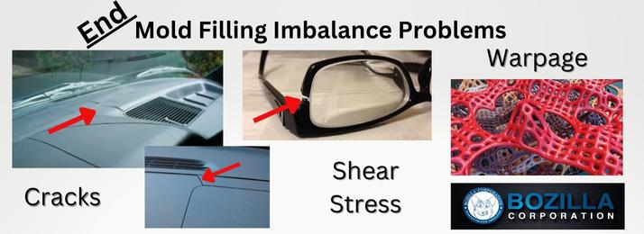
Medical device failure can be a devastating event Encountering negative physical and financial consequences is not the path a #medical company wants to take
Alleviate device failure

Should cost be the primary determining factor when developing and manufacturing a medical device?
Could that upfront cost savings result in more significant money expenditure due to law suites, fines, and time lost? Let’s consider a new approach
You can avoid expensive law suites, FDA fines, and loss of time by considering additional factors during the initial stages of development
These factors include:
- Polymer choice
- Consulting with an experienced #molding professional
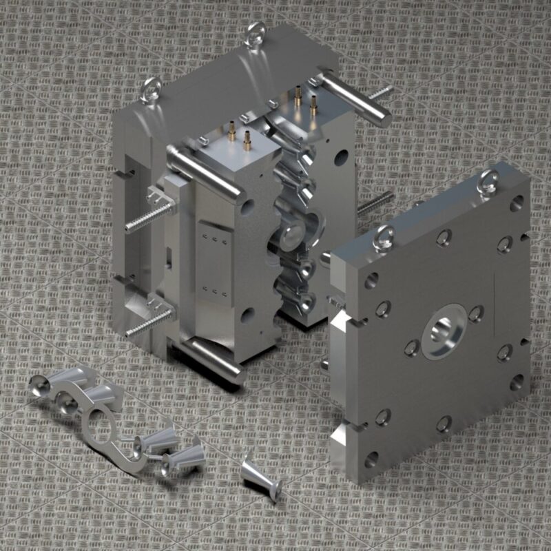
- Part design optimization utilizing experienced plastic engineers
You must have noticed that the word ‘experienced’ is used multiple times If you desire to manufacture a device successfully, it is vital to choose professionals who know what they are doing, from design creation to manufacturing Otherwise, you are at a greater risk of device failure
If cost is the only determining ingredient driving your decisions on any of the above considerations, you are putting your company and the patient at risk Gambling on any of the three factors above will reduce the chances of a successful medical device
Let’s get into it

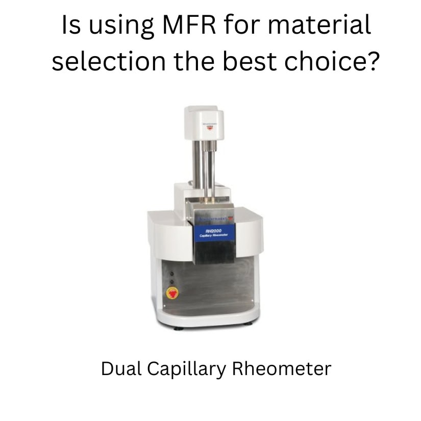
Polymer choice
What is significant about polymer choice?
Let’s recognize that an FDA-approved polymer is mandatory for most medical devices
From the polymer options the FDA endorses, which is best for your particular design? If you allow cost to drive this decision, it may come out poorly
At this stage, you should already be consulting a plastics engineer with extensive polymer knowledge The choice of polymer and its durability will depend on the device’s intended usage and exposure to environmental stresses
Injection Molding Consultant
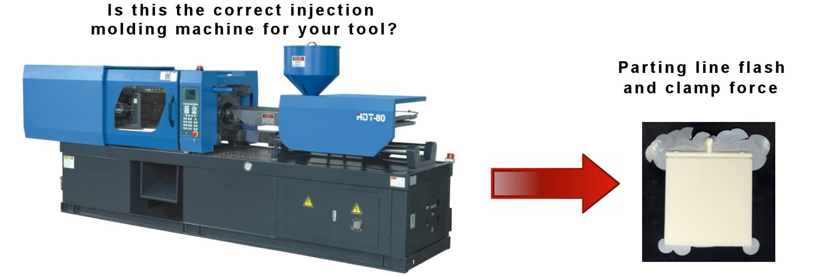
It is critical to have an experienced injection molding professional guide you when developing a design for a device A consultant with a plastic engineering degree is a significant advantage
Hold up if you are cringing because the costs in your head are adding up Let’s get through this bit, and I will show you how it saves you money in the long run
An experienced injection molding professional should have these qualifications:
- A minimum of 10 years in the injection molding industry
- Exposure to multiple industries, eg, automotive, caps and closures, medical, housewares, etc
- Fully understand how a polymer will respond during the injection molding process ( this will also affect your choice of polymer)