Tag: failure diagnosis

Recycled Resin- The Question and the Caution

By Bozilla
October 27, 2023

By: Bozilla Corporation


My customer doesn’t like using any recycled material

Working with a Tier 1 supplier to a major OEM, there was a discussion with the molders on the floor, people molding the parts on the injection molding machine, and their personal experiences

Their experience with recycled resins is the inability to maintain a controlled injection molding process

Because they are responsible for the quality of the part they are molding, they make decisions (call an audible) and replace the recycled resin with a locally available equivalent virgin resin This protects them from producing unacceptable

reclaimed plastic

Losing Control of the Process

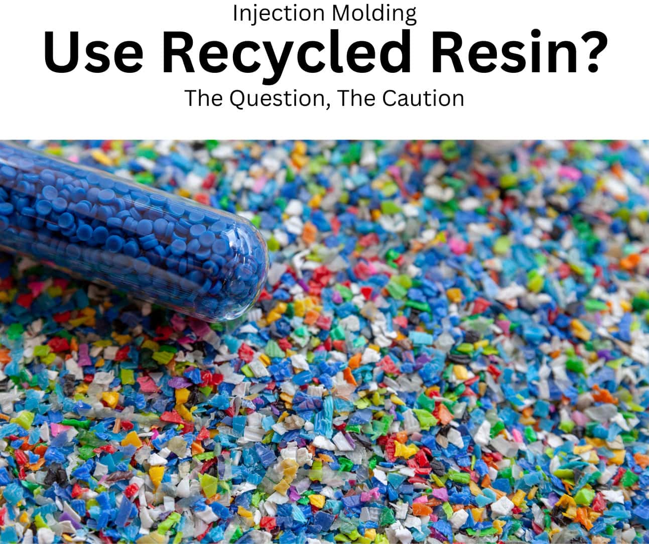
Recycled plastic goes through several processes when it is reclaimed  In layman’s terms, it gets beaten up

Here is the rundown:

In the first phase of the plastic recycling process, the material goes through the injection molding process, which partially degrades the material (molecular weight reduction)  Then, it is potentially exposed to UV, temperature fluctuations, or chemicals, which contributes to the degradation process  Next, the plastic is ground up and typically cleaned with a thermal or chemical process, further degrading the material  Finally, the reclaimed plastic is ready to, again, be beaten up in the injection molding machine

lose control of the process


Loss of injection molding process control

It is essential to know that the reclamation process breaks the polymer’s molecular structure down, making it lesser quality because the properties of that original polymer have been degraded  Recycled resin has a smaller molecular weight( length of chains) and varying viscosity, making it unpredictable  Virgin resin has molecular weight consistency/control with much less variation, giving it consistent properties

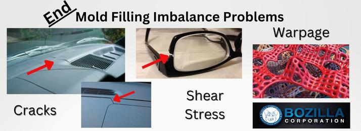
This lack of consistency, or better stated, lack of control of the recycled resin will affect the quality of your part

Do you see some reasons why you may reconsider using recycled plastic for your part?

Industry Response

Now, the response in the industry and all industries to using recycled materials is, when possible, to take a certain percentage of recycled material and blend it in with the virgin resin

However, it is essential to note that the percentage of added recycled material vs part quality is not a 1:1 ratio, eg, adding 20% of recycled resin does not equate to 20% loss of properties  For instance, you can test the recycled resin of 1 lot of material, and it may meet specs, but the next lot is completely different, thus knocking the process out of control  This lack of conformity

Read More

End Part Failure due to Mold Filling Imbalance

By Bozilla
June 7, 2023

Is Part quality and performance of your injection molded part important? Do you enjoy spending that extra time and money having your tool reworked? How about the pleasure of explaining the faulty part to your OEM? Let’s get real Balance your tool analytically before mold steel is cut-NO EXCEPTIONS! If you ignore this step, there is a decent chance of experiencing an unfavorable result on complex or seemingly simple tools

Let’s discuss mold balance

When can a mold-filling imbalance occur? These imbalances may be due to gate location(s) on the part, part geometry, or a combination of both Unless it is analyzed in flow simulation software, it is extremely challenging to determine how a part will fill

What creates an imbalance?

In a single cavity tool, an imbalance can occur when one location of the cavity finishes filling while another has yet to fill

In a multi-cavity tool and family tool, the same imbalance may occur within each cavity, but an imbalance may also arise from cavity to cavity

 How can imbalances cause problems with part quality and performance? 

 It is crucial to understand polymer flow A plastic engineer excels at possessing polymer knowledge Applying this expertise during the virtual optimization stage of your injection molded part will provide significant insight into an imbalance, which can affect part quality and performance

Where can an imbalance occur?

As the cavity fills, the temperature of the polymer flowing through the tool must not fluctuate to keep the properties of the polymer consistent throughout the cavity If flow velocity isn’t uniform in any region of the cavity, hesitation can occur and cause the polymer to cool down As the polymer cools, a frozen layer will form on the mold walls This frozen layer forms more rapidly in slower-moving regions and exceptionally fast in areas where the flow has stopped Once the cavity produces enough pressure to continue filling these hesitating regions, the flow will begin to move again However, the polymer is now cooler and will create tremendous shear stress as it continues to fill the remainder of the cavity THIS SHEAR STRESS WILL CREATE THE POTENTIAL FOR PART DEFLECTION AND EVEN PART FAILURE

If imbalances occur in a multi or family tool, the entire cavity experiencing the hesitation is at risk for this increased shear stress The imbalance also causes the hesitating region of the cavity to become non-uniformly packed, which translates into non-uniform shrinkage, another precursor to part warpage

shear in polymer

How does

Read More

STOP doing this to Cooling Circuits!

By Bozilla
May 2, 2023

STOP ignoring the importance of proper cooling circuit design for injection molding Cooling circuit design is typically not heavily weighted with regards to importance in the injection molding industry Cooling circuits need to be designed properly and the importance of the design must not be overlooked A common practice is to simply ‘place cooling in the mold’ and not much more Sometimes it is taken a step further where the practice is ‘to place as much cooling in the mold as possible’ This is a better practice but is it the best? We are going to discuss the importance of proper cooling circuit design and the implications of overlooking this important practice

Cooling Circuit Diameter

Is the diameter of the cooling circuit important? It certainly is In fact, the diameter of the cooling circuit must be a part of a larger consideration such as circuit spacing, pressure drop and flow rates A larger diameter may be thought to cool better since it is larger, which is somewhat true, however it will take up more space due to its larger diameter so it may be difficult to route in tighter locations

The spacing of larger cooling lines can be increased based on the diameter which can result in fewer cooling lines hence less gun—drilling, ie a cost savings but this is not always the better condition if the mold design is complex or small  Larger cooling lines will also have a lower pressure loss resulting in less power required to pump the water through the circuit This is a big plus but the difference in pumping efficiency may be negligible It is also important to understand that varying cooling circuit diameters within the same mold will only be as efficient as the smallest diameter of that circuit due to the higher pressure loss within the section containing the smaller diameter The flow may be turbulent in the portion with the smaller diameter yet may take flow away from the larger diameter portion resulting in a laminar flow condition in the section with that larger diameter

The Importance of Balanced Cooling Circuits

Optimal designed cooling circuits are the driving force behind productivity and cycle times

If your cooling circuits are not as working as efficiently as they can be, they will be costing you precious time and money Balancing cooling circuits plays a tremendous role in cooling efficiency

So why do the cooling circuits need to be balanced and what exactly does that mean?

In short, all circuits are not created equal If cooling circuits are not equally balanced, then the flow rate

Read More

Using Aluminum for Injection Molds?

By Bozilla
July 14, 2022

Aluminum tooling has significant benefits when compared to steel tooling because of the cost of aluminum as well as the ease of manufacturing Aluminum tools can be cut much quicker than steel saving a lot of time and money These benefits can result in shorter cycle times and price-per-part savings However, there are some drawbacks of aluminum such as being a softer metal which can cause mold deflection and also having a fatigue limit which can be catastrophic In order to better understand the advantages and disadvantages of utilizing aluminum for injection molds we will take a closer look at the properties of both aluminum and steel

Let’s compare the properties of aluminum to steel

Table of Aluminum v Steel properties

aluminum v steel table

The above table compares the properties of aluminum and steel Based on this table, we can determine the following

Density:                                  Aluminum is 279 times less dense than Steel

Hardness:                               Aluminum is much softer than steel

Thermal Conductivity:          Aluminum is 655 times more conductive than Steel

Thermal Diffusivity:              Aluminum has 79 times the thermal diffusivity than Steel

Yield Strength:                      Aluminum has almost half of the yield strength of Steel

Poissons Ratio:                      Aluminum deforms more than Steel

 Advantages of Using Aluminum for Injection Molds

 Now that we’ve compared aluminum to steel, we can take a look at the advantages of using aluminum for injection molds based on the above properties

Density:

 Aluminum is 279 times less dense than steel resulting in a lighter end product As the cost of shipping is increasing dramatically, the weight of any product will have a direct impact on shipping costs and must be kept low as possible

Hardness:

The softer aluminum reduces machining hours and wear and tear on machining components

Thermal Conductivity and Diffusivity:

Thermal conductivity and diffusivity is extremely important in injection molding as it directly impacts the cycle time Aluminum is 655 times more conductive and 799 times the diffusivity of steel which results in a significant reduction in cycle time, faster start-up times, reduction in response times to process temperature changes, and mold change times

The faster thermal recovery of aluminum also modulates the cyclic ‘highs-and lows’ of the tool temperature during processing As the melt is injected into the mold, the heat must be removed as quickly as possible Aluminum is able to process the heat out of the tool much faster than steel resulting in a more stable mold temperature and thus a more stable process

Disadvantages of Using Aluminum for Injection Molds

Poissons Ratio:

The Poissons Ratio of Aluminum is 033 and Steel

Read More

Creating a Virtual Plastics Injection Molding Window

By Bozilla
April 27, 2022

Since the inception of plastic injection molding, creating a robust injection molding process has always been a challenge As time has progressed, the design of plastic parts has become more detailed and intricate, the tolerances have become tighter and the boundaries of injection molding standards are being pushed to their limits The combination of each one of these factors is making it more and more difficult to create and maintain a robust molding process

Initially, it wasn’t difficult to design a basic injection molding window that would result in a robust molding process However, with the advent of increasingly demanding factors it has become more difficult to design a process molding window that is large enough to be robust and create consistently good parts As a matter of fact, not only is it difficult to create a wide process molding window, it’s nearly impossible to create a suitable molding window- Period We will discuss how and why it is necessary to first create a virtual injection molding window and how that data can be translated to the floor in order to have the best injection molding window possible

Let’s begin with understanding what a molding window (or process window) is Typically, a molding window is comprised of three major factors: Fill time (or fill speed), Mold Temperature and Melt Temperature Each of these factors has the greatest impact on the injection molding process

Graphs below will illustrate the impact of each

The influence of each factor:

  • Fill Time (fill speed): As fill speed decreases, the material moves into and through the cavity slowly which allows the cooling effects of the tool steel to have more time to influence and cool the temperature of the plastic resulting in a higher viscosity response and a greater pressure to fill the cavity Conversely, as the fill speed increases, the material will shear thin (the viscosity will decrease) significantly, but ultimately the plastic will resist filling the cavity and require a greater pressure to fill the cavity Somewhere between filling extremely slow and filling extremely fast is a sweet spot that requires low pressure to fill the cavity If plotted out in a graph, it will be a u-shaped curve where the lowest point is typically a good fill speed

molding window pressure

  • Mold Temperature: The mold temperature is highly influential with regards to having the material fill the cavity The thickness of the part relative to the flow length is an important relationship with regards to the impact of the mold
Read More

The Reality of Core Shift- Is this happening to You?

By Bozilla
March 23, 2022

Core shift is not always obvious or suspected Recently, Bozilla Corporation was called upon to investigate a part that was warping differently and more than expected The customer had a flow simulation conducted by a third party and the warpage results did not match the actual part data Sometimes part warpage does not match the flow simulation and in many cases, it is easily explained However, after a quick investigation, the underlying cause of the excessive deflection was not easily understood It was time for our Team to troubleshoot

(The animations and images presented in this article do not represent the Customers actual part file and is just an example of how core deflection occurs)

Core deflection fill time graph

To begin the investigation, we compared the floor process to the simulation, which is standard operating procedure They matched fairly well They are never a perfect match but were very close We then looked at the part data and tool design then compared it to the data utilized in the flow analysis The data matched This was good news because through process of elimination, we were nearing the target

We then began taking a closer look at the part along with the flow simulation results We noticed that there were long features extending from the core side of the tool that the polymer had to flow around and down The features were thin so they did not have cooling in them therefore it was suspected that these long cores were heating up excessively causing the polymer to stress relieve and therefore warp However, the simulation software accounted for this to some degree and we did not see a trend that suggested the hot core feature was contributing to additional deflection

Having a long history with examining many polymers and how they behave in varying geometries caused us to take a closer look at the differential pressure within the cavity as it flowed around and along the long core features We discovered a significant pressure differential that occurred on either side of the core We also learned that the polymer did not freeze uniformly around that core during the 2nd stage pack process Having differential pressure and non-uniform freezing threw up a few flags

Core shift pressure graph

We had to investigate the impact of the differential pressure and non-uniform freezing on these features We knew it was time for a core-deflection analysis The customer was fairly confident that the P-20 tool steel was robust enough to

Read More

Failure Diagnosis-Product & Process

By Bozilla
August 12, 2021

Bozilla Corporation’s core business is performing CAE analyses, specifically mold flow analyses, on products to optimize both design and process Our procedures and standards set a benchmark to create the highest degree of part quality with the least amount of difficulty and waste

Because many companies have not used FEA, they are turning to the injection molding specialists at Bozilla Corp with issues relating to part failure or processing problems Fortunately, we are solving many of them with Failure Diagnosis

What exactly is Failure Diagnosis?

Failure Diagnosis is the process of identifying why a product or process isn’t performing properly

The injection molding professionals at Bozilla Corporation have cultivated and executed proven techniques to execute this vital task and resolve our customers’ concerns on all levels

This type of diagnosis requires calculated procedures and thorough knowledge in:

✔ CAE Analysis

✔ Root Cause Analysis

✔ Experience with similar products/issues

✔ Indepth knowledge of polymers

If you are experiencing problems with a product in the field or with its process, we will implement our procedures to assist in solving these issues

 Some examples may include:

➤ Start up times for a tool are taking longer than expected, the process is difficult to stabilize, or the start up time on the same tool varies from machine to machine

➤ The process has variation and too many bad parts are being produced

➤ The parts seem to be fine but are failing in the field which causes customer dissatisfaction and more work/costs for you

As an added bonus, the Failure Diagnosis procedures can further lean your process and potentially save you money

Bozilla Corporation has worked extensively with companies to resolve their injection molding performance issues Contact us today and find out how we can help diagnosis any issues you may be having with your injection molding product and/or process and get you back on track!


wwwBozillaCorpcom

We Know Injection Molding! Plastics Engineering, Consulting, Optimization, Failure Diagnosis, Training

About the author

Chris Czeczuga is a Plastics Engineer, Injection molding expert, Military Veteran and the President of Bozilla Corporation He has proven success with many OEM’s Tier 1’s, Tier 2’s, Tool Shops, Molding shops, Part Designers, Processors and Fortune 500 companies throughout the injection molding industry A graduate from UMass Lowell, he is Expert Certified with Autodesk, has 20 years of field experience, intimate knowledge of injection molding part, tool and feed system design Bozilla Corporation’s success is built on providing the highest level of injection

Read More

Actual Injection Molded Part differs from Analytical Prediction

By Bozilla
July 28, 2021

In this discussion, we will explore a part that was injection molded and scanned for deflection Interestingly, the actual deflection did not match that of the analyzed part Unfortunately, this can sometimes happen and when it does, it is the responsibility of the software expert to investigate why the predicted analysis results are not matching the floor results This can be a challenging task

In the engineering world, it is common to hear the phrase ‘garbage in equals garbage out’ In other words that phrase means that all inputs plugged into any set of calculations will directly influence the outcome of those calculations When it comes to FEA, having correct input data is especially critical since technical software can only be as good as what is entered into each specific section But what steps should be taken if you have ensured that the analysis is set up correctly yet, the analytical results do not match the results on the floor? In the sample study below, we will take a closer look
For this study, we will look at a part that we will call the ‘console’:

Console Fill Console DeflectionConsole


We will compare the analytical inputs to the inputs used on the floor Then, we will explore how the analytical results compare to those on the floor

In preparation for any analysis, the user must take the necessary precautions to ensure that the inputs in the mold filling software are as accurate as possible

Part model

1) Is the part model prepared so that it meets or exceeds the standards that the software supplier recommends?

Yes, the part was modeled as a 3D model and exceeds the recommended criteria

Feed system design

2) Does the feed system match the final design of the finished product?

Yes, it was designed per the specifications provided by the tool shop

Material data

3) Is the material data in the analysis the same as what is being used on the floor?

Yes

   Is the material card comprehensive ie, is it fully characterized?

Yes

Process inputs

4) Do the process inputs in the software match the floor inputs?

Yes, see the Table 1 Below

analytical process setting vs floor process setting


Once the inputs have been confirmed as optimal and correct, we inspect the results and compare them

First, we examine the filling pattern to see if it is predicted correctly
To determine the correlation of flow patterns between Moldflow and

Read More