Tag: plastics engineering

Is Using MFR the Best method for Material Selection?

By Bozilla
December 1, 2022

When a material selection comes down to flow rate, is using the (Mass Flow Rate) MFR or Melt Index (MI) the best choice? To answer this, we need to understand why the Melt Index test initially came about

The Origin of the Melt Index Test Method (ASTM D-1238)

ASTM D 1238: Test Method for Flow Rates of Thermoplastics by Extrusion Plastometer

Before there were standards to test polymers, there was a need to determine the differences in how polymers would flow when melted A method was created to keep all polymers on the same level playing field This method places the material in an Extrusion Plastometer or Melt Indexer

furnace of the plastometer and extrusion plastometer

The standard has the barrel of the melt indexer heated to a specific temperature The user would obtain a resin sample and place it in the barrel where a piston would be inserted A specific load would be placed on the piston, and the melted polymer would be extruded through a capillary die (with a particular orifice size) The extrusion would take place for 10 minutes, and the amount of polymer would be weighed in grams yielding an output in g/10 minutes

Having MFR data for all materials allows one to compare them side-by-side, giving a respective idea of how each will flow with the other

The limitation of this test method is that it is, in fact, one point on the viscosity curve and is at a shear rate of nearly zero, which is not indicative of the injection molding process

When materials experience shear during injection molding, shear rates may be experienced up to and possibly exceeding 100,000 1/sec Some materials become more viscous at higher shear rates, but these are uncommon

So how do we compare materials at these higher shear rates?

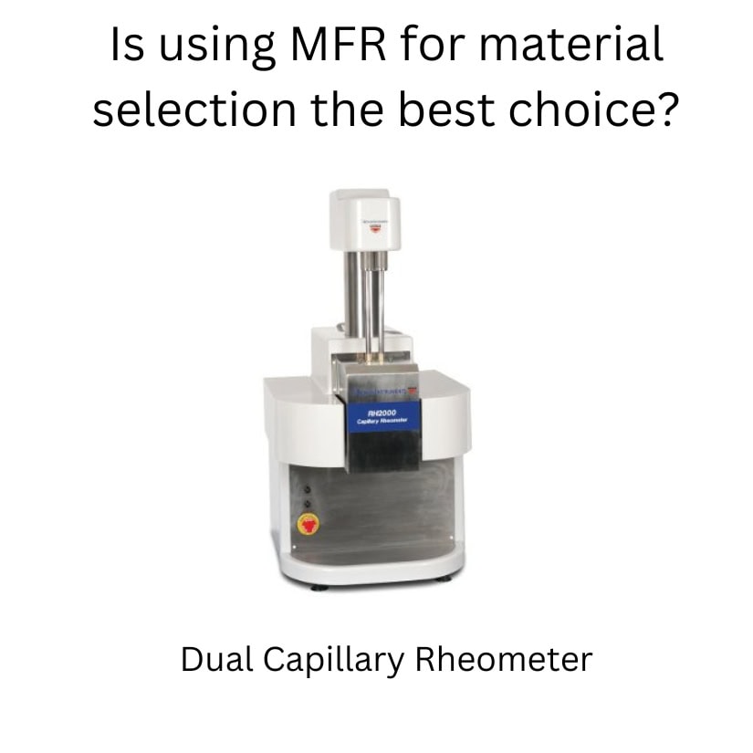
Since the inception of the melt indexer (1950s), a much more accurate test method was designed using a Dual Capillary Rheometer

Dual capillary rheometer

A dual capillary rheometer can produce a series of viscosity data points over a range of shear rates, such as the image below

rheology curve

A Rheology curve provides exact viscosity data based on specific shear rates at specifically tested temperatures Notice how the Melt Index MFR point does not provide any data relating to the injection molding process A curve like this will allow one to understand the exact behavior of the material and shear rate

Read More

Using Aluminum for Injection Molds?

By Bozilla
July 14, 2022

Aluminum tooling has significant benefits when compared to steel tooling because of the cost of aluminum as well as the ease of manufacturing Aluminum tools can be cut much quicker than steel saving a lot of time and money These benefits can result in shorter cycle times and price-per-part savings However, there are some drawbacks of aluminum such as being a softer metal which can cause mold deflection and also having a fatigue limit which can be catastrophic In order to better understand the advantages and disadvantages of utilizing aluminum for injection molds we will take a closer look at the properties of both aluminum and steel

Let’s compare the properties of aluminum to steel

Table of Aluminum v Steel properties

aluminum v steel table

The above table compares the properties of aluminum and steel Based on this table, we can determine the following

Density:                                  Aluminum is 279 times less dense than Steel

Hardness:                               Aluminum is much softer than steel

Thermal Conductivity:          Aluminum is 655 times more conductive than Steel

Thermal Diffusivity:              Aluminum has 79 times the thermal diffusivity than Steel

Yield Strength:                      Aluminum has almost half of the yield strength of Steel

Poissons Ratio:                      Aluminum deforms more than Steel

 Advantages of Using Aluminum for Injection Molds

 Now that we’ve compared aluminum to steel, we can take a look at the advantages of using aluminum for injection molds based on the above properties

Density:

 Aluminum is 279 times less dense than steel resulting in a lighter end product As the cost of shipping is increasing dramatically, the weight of any product will have a direct impact on shipping costs and must be kept low as possible

Hardness:

The softer aluminum reduces machining hours and wear and tear on machining components

Thermal Conductivity and Diffusivity:

Thermal conductivity and diffusivity is extremely important in injection molding as it directly impacts the cycle time Aluminum is 655 times more conductive and 799 times the diffusivity of steel which results in a significant reduction in cycle time, faster start-up times, reduction in response times to process temperature changes, and mold change times

The faster thermal recovery of aluminum also modulates the cyclic ‘highs-and lows’ of the tool temperature during processing As the melt is injected into the mold, the heat must be removed as quickly as possible Aluminum is able to process the heat out of the tool much faster than steel resulting in a more stable mold temperature and thus a more stable process

Disadvantages of Using Aluminum for Injection Molds

Poissons Ratio:

The Poissons Ratio of Aluminum is 033 and Steel

Read More

Homopolymer vs. Copolymer

By Bozilla
May 24, 2022

Material selection for an injection molding application can sometimes prove to be very challenging What happens if you identify a material then find that it can be supplied as a homopolymer or a random copolymer Is there a difference? The answer is YES The choice made for your project can affect part quality  

The Homopolymer:

homopolymer chain

A homopolymer has the same base unit which causes the molecular chain to have a high degree of consistency and size However, length can vary depending on how long the polymerization process is allowed to occur

The high degree of consistency in a homopolymer creates a high degree of regularity When many of these changes flow and combine, they are able to create a very tight entanglement and when they cool and shrink, they also have a high degree of crystallinity which increases shrink

The Copolymer:

copolymer chain

A copolymer, as shown in the image above, has more than one base unit and each base unit is a different size There can be more than two base units Due to the variation in size of the base units, the copolymer chains will be spaced much further from each other and have a higher degree of irregularity And similar to the homopolymer, the length of the molecule will depend on how long the polymerization process is allowed to occur

The high degree of irregularity does not allow the polymer chains to form a tight structure, leaving a lot of space between the molecular chains Therefore, when the polymer flows, there can be alignment but there will be more irregularity and not as tight of a structure which prevents excessive shrinkage

When comparing the two types of polymers, assuming each is the same length (same molecular weight, per se) the homopolymer will be much more organized and structured therefore creating more mechanical strength and chemical resistance but have high shrinkage The copolymer will have more random orientation which will create space between the molecules allowing for easier chemical attack and less mechanical strength and also have lower shrinkage Of course, we could discuss these comparisons in much more detail but we will stick to the basics for now

As material selection relates to injection molding, the properties of the material is a crucial factor

The major properties when comparing homopolymers to copolymers are:

  • shrinkage
  • chemical resistance
  • mechanical strength

Each of these properties must be considered with regards to the outcome of part quality

For example, when injection molding

Read More

Creating a Virtual Plastics Injection Molding Window

By Bozilla
April 27, 2022

Since the inception of plastic injection molding, creating a robust injection molding process has always been a challenge As time has progressed, the design of plastic parts has become more detailed and intricate, the tolerances have become tighter and the boundaries of injection molding standards are being pushed to their limits The combination of each one of these factors is making it more and more difficult to create and maintain a robust molding process

Initially, it wasn’t difficult to design a basic injection molding window that would result in a robust molding process However, with the advent of increasingly demanding factors it has become more difficult to design a process molding window that is large enough to be robust and create consistently good parts As a matter of fact, not only is it difficult to create a wide process molding window, it’s nearly impossible to create a suitable molding window- Period We will discuss how and why it is necessary to first create a virtual injection molding window and how that data can be translated to the floor in order to have the best injection molding window possible

Let’s begin with understanding what a molding window (or process window) is Typically, a molding window is comprised of three major factors: Fill time (or fill speed), Mold Temperature and Melt Temperature Each of these factors has the greatest impact on the injection molding process

Graphs below will illustrate the impact of each

The influence of each factor:

  • Fill Time (fill speed): As fill speed decreases, the material moves into and through the cavity slowly which allows the cooling effects of the tool steel to have more time to influence and cool the temperature of the plastic resulting in a higher viscosity response and a greater pressure to fill the cavity Conversely, as the fill speed increases, the material will shear thin (the viscosity will decrease) significantly, but ultimately the plastic will resist filling the cavity and require a greater pressure to fill the cavity Somewhere between filling extremely slow and filling extremely fast is a sweet spot that requires low pressure to fill the cavity If plotted out in a graph, it will be a u-shaped curve where the lowest point is typically a good fill speed

molding window pressure

  • Mold Temperature: The mold temperature is highly influential with regards to having the material fill the cavity The thickness of the part relative to the flow length is an important relationship with regards to the impact of the mold
Read More

The Reality of Core Shift- Is this happening to You?

By Bozilla
March 23, 2022

Core shift is not always obvious or suspected Recently, Bozilla Corporation was called upon to investigate a part that was warping differently and more than expected The customer had a flow simulation conducted by a third party and the warpage results did not match the actual part data Sometimes part warpage does not match the flow simulation and in many cases, it is easily explained However, after a quick investigation, the underlying cause of the excessive deflection was not easily understood It was time for our Team to troubleshoot

(The animations and images presented in this article do not represent the Customers actual part file and is just an example of how core deflection occurs)

Core deflection fill time graph

To begin the investigation, we compared the floor process to the simulation, which is standard operating procedure They matched fairly well They are never a perfect match but were very close We then looked at the part data and tool design then compared it to the data utilized in the flow analysis The data matched This was good news because through process of elimination, we were nearing the target

We then began taking a closer look at the part along with the flow simulation results We noticed that there were long features extending from the core side of the tool that the polymer had to flow around and down The features were thin so they did not have cooling in them therefore it was suspected that these long cores were heating up excessively causing the polymer to stress relieve and therefore warp However, the simulation software accounted for this to some degree and we did not see a trend that suggested the hot core feature was contributing to additional deflection

Having a long history with examining many polymers and how they behave in varying geometries caused us to take a closer look at the differential pressure within the cavity as it flowed around and along the long core features We discovered a significant pressure differential that occurred on either side of the core We also learned that the polymer did not freeze uniformly around that core during the 2nd stage pack process Having differential pressure and non-uniform freezing threw up a few flags

Core shift pressure graph

We had to investigate the impact of the differential pressure and non-uniform freezing on these features We knew it was time for a core-deflection analysis The customer was fairly confident that the P-20 tool steel was robust enough to

Read More

Accuracy of Flow Simulation on Plastics Injection Molding machine

By Bozilla
March 15, 2022

I have recently been exposed to multiple articles and discussions regarding the implementation of flow simulation on injection molding machines This is an intriguing topic which I advocate Currently, this new combo method is proving difficult to line up the results from the analysis with the actual process on the injection molding machine In order to successfully utilize this capability on an injection molding machine, several factors must be understood

For those who have read my previous articles, you may appreciate that I strongly promote having the right person for the right job In other words, the simulation engineer must have a complete and comprehensive understanding of plastics in order to be able to properly simulate the plastics injection molding process

My suggestion is to always have a degreed Plastics Engineer with floor experience perform simulations on plastic parts The reason for this advocation is to ensure that the simulation engineer virtually takes on the role of the process engineer This makes certain that the simulation will properly emulate the injection molding machine process on the part being molded Unfortunately, this is not always the case and the articles I have recently read do not touch on this very important factor A virtual simulation cannot simply be executed, have the results taken to the floor, input into the injection molding machine and expect the molded part to perfectly match the simulation results It’s not that easy due to many variables which must be considered

Plastics injection molding optimization

For example, the simulation engineer (with the proper degree and experience) will understand the limitations and boundaries of the intended injection molding machine for that particular simulated part It is not always necessary to know every specification of the machine and to input that specific data into the simulation Most machines have a wide variation of capabilities that the simulation engineer will take into consideration The simulation will then be executed with all of the necessary variables factored in for the injection molding machine, thus maintaining a high degree of accuracy between the simulation and the floor

The difficult task is discovering those unintended variables that affect the process on the floor, eg material batch changes, colorant issues in the polymer, tool temperature variations that the press cannot record, physical changes within the tool such as polymer sticking to action within the tool, cold gates not opening and flowing when desired, cosmetic issues at the gate or

Read More

Is this the correct Injection Molding Machine for your Tool?

By Bozilla
November 8, 2021

To start this discussion I’d have to first state that the size of the tool plays a large role when selecting an injection molding machine  More specifically, it is the projected area that is of concern and how the projected area, along with the pressure distribution over that projected area, creates clamp force

Selecting a machine based on clamp force (tonnage) is more common when you have a part with a large projected area; ie multi-cavity tools, bumper fascias, housewares and many other items

In today’s economic climate, it’s more important than ever to conserve energy  Many believe that using the smallest IMM is the best way to achieve this cost savings  However, there are reasons why a smaller machine isn’t always the most efficient machine

 Reason 1: If an optimum process is the objective, select a machine that does not allow the tool to exceed the clamp force and flash the tool (blowing open)  during an  ‘optimized’ process

We  have had many concerned customers consult with us about the process Their questions are directed at finding out why the part is warping or exhibiting cosmetic defects  Once I dig into the process, I typically find that the part is not packed sufficiently due to the tool blowing open  In order to keep the tool closed, they must pack with very little pressure for a very short time  Packing with too little pressure, too little time, or both can cause a loss of control with dimensional stability and/or cosmetic issues due to excessive shrinkage  These issues create problems that are caused because the tool is in an IMM that doesn’t have the proper clamp force requirement

In the image below the clamp force required to fill and make the part is 250 Tons  However, in order to pack the part out sufficiently and make a good part (meets tolerances, minimal cosmetic defects, minimal deflection, etc) the clamp force required during 2nd stage pack is 1,450 Tons  That’s a very big difference

clamp force plot


 Reason 2: You are able to make parts but the process window is so small that staying within the process window is difficult or impossible to maintain

The inability to stay within a process window could be caused by several issues, especially since there are so many variables in the molding process  However, if the machine does not have sufficient clamp force to stay closed during an optimum molding process, concessions will be made and

Read More

Valve Gates and Sequencing-for injection molding

By Bozilla
August 24, 2021

Valve Gates are invaluable as they relate to their primary design purpose and have many important functions

 They can:

✔ Eliminate waste that cold runners create

✔ Eliminate vestige

✔ Be sequenced

✔ Eliminate weld lines

✔ Control filling patterns

However, users should be aware that there are a few potential issues that could come with using valve gates and sequencing

valve gates for injection molding

 Vestige v Witness Marks

Valve gates can minimize or completely remove vestige by direct gating on the part  They do leave witness marks on the part where the valve gate tip seats into the cavity but with proper grinding or surface finish, it can be minimized or completely hidden

 Controlling the Fill Pattern v Machine Stroke Programming

When multiple valve gates are used to fill a part, it may be necessary to time the sequencing in order to create a more uniform filling pattern  It is extremely important to understand that if the valve gates are sequenced, then the flow rate input must also match the demand of the feed system

For example: If your tool has four valve gates and you initially open two valve gates, then open the next two valve gates, the IM machine must deliver twice the flow rate when the two additional valve gates are opened in order to maintain equal flow rates through all nozzles in the feed system

If the machine stroke is not profiled to compensate for the flow rate demand, the properties of the polymer will change in the cavity due to different filling rates  This could translate into non-uniform shrinkage and stress which directly translates into warpage  It can also cause surface finish variations as shown in the picture below

Nozzle and machine pressure for injection molding

Cascade Sequencing (eliminate weld lines) v Machine Stroke Programming

If the intention is to sequence the valve gates as the flow front passes by in order to remove weld lines, then the same concerns arise if the machine stroke is not programmed to compensate for the additional flow rate demand as additional nozzles are opened

Cascade sequencing can also create back-flow and uneven packing along with uneven stress even if the machine stroke is profiled to compensate for flow rate

Cascade sequencing removes weld lines, therefore the potential problems that accompany it must be weighed  Cascade sequencing should be used as a last resort when trying to eliminate weld lines

Valve Pin Control

Hot runner manufacturers have now developed controllers to

Read More

Can Gate Location Really affect Part Warpage?

By Bozilla
August 17, 2021

Based on part geometry, gate location(s) will determine how the polymer fills the cavity  If the cavity doesn’t fill in a balanced/uniform fashion, the internal stresses will be anisotropic- meaning non-uniform properties  So it is important to place a gate in a location such that the polymer flowfront fills the cavity at a uniform rate and reaches the end of the cavity at all locations, including weld line locations, simultaneously

With simple part geometry, identifying an ideal gate location may be possible by using experience and examining the part  However, with more complex geometry and gating limitations (cooling line interference, ejector pin interference, slides, etc), it is nearly impossible to determine the appropriate gate location(s) without using FEA(flow simulation)  Not only can FEA(flow simulation) produce actual deflection results(warpage), it can also provide data that is a precursor to warpage-such as volumetric shrinkage and frozen-in stress which is typically due to a response from forcing the material into the cavity while the material is trying to freeze

gate location and part warpage courtesy of sciencedirectcom

Gate location(s) will determine polymer orientation  Based on that location, it will ultimately determine polymer shrinkage  Also, different regions of the part will cool at different rates(regions of the cavity near the gate that were first to fill will cool before regions furthest from the gate)


Why is this important?  Because there are 3 major components that contribute to warpage:

 Polymer Orientation

Polymer Shrinkage

Cooling Effects


Shrinkage and orientation are both directly correlated to injection location(s) on a part as it relates to processing conditions  Warpage due to cooling effects is  based on the rate of how the polymer cools on one side of the cavity relative to the other side Non-uniform cooling through the thickness will create warpage

Because gate location(s) directly correlates to the contributors of warpage, gate location is therefore extremely important in the tool creation process and ultimately the quality of the part

The injection molding professionals at Bozilla Corporation have over 20 years of experience assisting OEM’s, Tier 1 & Tier 2 suppliers, and Tool Shops to create quality parts that meet timing and goals

wwwBozillaCorpcom


About the author

Chris Czeczuga President Bozilla Corporation

Chris Czeczuga is a Plastics Engineer, Injection molding expert, Military Veteran and the President of Bozilla Corporation He has proven success with many OEM’s Tier

Read More

Actual Injection Molded Part differs from Analytical Prediction

By Bozilla
July 28, 2021

In this discussion, we will explore a part that was injection molded and scanned for deflection Interestingly, the actual deflection did not match that of the analyzed part Unfortunately, this can sometimes happen and when it does, it is the responsibility of the software expert to investigate why the predicted analysis results are not matching the floor results This can be a challenging task

In the engineering world, it is common to hear the phrase ‘garbage in equals garbage out’ In other words that phrase means that all inputs plugged into any set of calculations will directly influence the outcome of those calculations When it comes to FEA, having correct input data is especially critical since technical software can only be as good as what is entered into each specific section But what steps should be taken if you have ensured that the analysis is set up correctly yet, the analytical results do not match the results on the floor? In the sample study below, we will take a closer look
For this study, we will look at a part that we will call the ‘console’:

Console Fill Console DeflectionConsole


We will compare the analytical inputs to the inputs used on the floor Then, we will explore how the analytical results compare to those on the floor

In preparation for any analysis, the user must take the necessary precautions to ensure that the inputs in the mold filling software are as accurate as possible

Part model

1) Is the part model prepared so that it meets or exceeds the standards that the software supplier recommends?

Yes, the part was modeled as a 3D model and exceeds the recommended criteria

Feed system design

2) Does the feed system match the final design of the finished product?

Yes, it was designed per the specifications provided by the tool shop

Material data

3) Is the material data in the analysis the same as what is being used on the floor?

Yes

   Is the material card comprehensive ie, is it fully characterized?

Yes

Process inputs

4) Do the process inputs in the software match the floor inputs?

Yes, see the Table 1 Below

analytical process setting vs floor process setting


Once the inputs have been confirmed as optimal and correct, we inspect the results and compare them

First, we examine the filling pattern to see if it is predicted correctly
To determine the correlation of flow patterns between Moldflow and

Read More