Tag: plastics expert

Homopolymer vs. Copolymer

By Bozilla
May 24, 2022

Material selection for an injection molding application can sometimes prove to be very challenging What happens if you identify a material then find that it can be supplied as a homopolymer or a random copolymer Is there a difference? The answer is YES The choice made for your project can affect part quality  

The Homopolymer:

homopolymer chain

A homopolymer has the same base unit which causes the molecular chain to have a high degree of consistency and size However, length can vary depending on how long the polymerization process is allowed to occur

The high degree of consistency in a homopolymer creates a high degree of regularity When many of these changes flow and combine, they are able to create a very tight entanglement and when they cool and shrink, they also have a high degree of crystallinity which increases shrink

The Copolymer:

copolymer chain

A copolymer, as shown in the image above, has more than one base unit and each base unit is a different size There can be more than two base units Due to the variation in size of the base units, the copolymer chains will be spaced much further from each other and have a higher degree of irregularity And similar to the homopolymer, the length of the molecule will depend on how long the polymerization process is allowed to occur

The high degree of irregularity does not allow the polymer chains to form a tight structure, leaving a lot of space between the molecular chains Therefore, when the polymer flows, there can be alignment but there will be more irregularity and not as tight of a structure which prevents excessive shrinkage

When comparing the two types of polymers, assuming each is the same length (same molecular weight, per se) the homopolymer will be much more organized and structured therefore creating more mechanical strength and chemical resistance but have high shrinkage The copolymer will have more random orientation which will create space between the molecules allowing for easier chemical attack and less mechanical strength and also have lower shrinkage Of course, we could discuss these comparisons in much more detail but we will stick to the basics for now

As material selection relates to injection molding, the properties of the material is a crucial factor

The major properties when comparing homopolymers to copolymers are:

  • shrinkage
  • chemical resistance
  • mechanical strength

Each of these properties must be considered with regards to the outcome of part quality

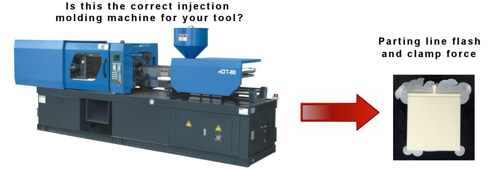
For example, when injection molding

Read More

Key Factors in a Reliable Plastics Injection Molding Simulation Report

By Bozilla
November 30, 2021

I have written in a prior post about the key factors necessary in a plastics injection molding optimization analyst  Now, I would like to discuss the importance of a skillfully assembled simulation report  Jennifer Schmidt spoke of the key ingredients of a trustworthy injection molding simulation report in her talk at the Plastics Technology Molding 2021 conference In this brief, I will discuss the valuable information she provided and add additional feedback  If you want a successful outcome for your tool, these key components are essential to consider


Injection Molding simulation software

1Software

  • What version is being used and is the software up to date? Look for signs that the analyst is using an older version of software which will alter the results on the report, and ultimately the floor results

Typically, the output file(s) of the software contain the release version of the software  It might not be the absolute latest release of the software, but is should be a proven release which is typically a year old or less

Mesh quality for injection molding

2 Type of Mesh used: Consider the type of mesh that used for the part and the runner

  • Is the mesh type appropriate for the part geometry?
  • Is it precise enough in critical areas to capture important details?
  • Is the correct technology being used for the part geometry/runner combination, ie midplane, Dual-Domain, 3D or a specialty mesh used?
  • Will the report allow access to display the mesh?
  • Does the filling animation, weld lines and sink marks reveal insights into the mesh quality?

Consider: Simulations of the same part with the same material and same mesh density, but different mesh types for the part and runner, may produce different results for pressure at the fill-to-pack switchover point, which could make quite a difference in what occurs in an actual molding environment

There are many factors to consider and only a seasoned user with the proper education in the software will be able to make these determinations in order to provide the best analytical outcome

Material Data for injection molding


3 Material Data: An accurate molding prediction requires good material data

  • What was the material data in the simulation based on?
  • Was data on the actual material available?
  • Was the data a substitute?-a resin of the same generic family but has a
Read More

Is this the correct Injection Molding Machine for your Tool?

By Bozilla
November 8, 2021

To start this discussion I’d have to first state that the size of the tool plays a large role when selecting an injection molding machine  More specifically, it is the projected area that is of concern and how the projected area, along with the pressure distribution over that projected area, creates clamp force

Selecting a machine based on clamp force (tonnage) is more common when you have a part with a large projected area; ie multi-cavity tools, bumper fascias, housewares and many other items

In today’s economic climate, it’s more important than ever to conserve energy  Many believe that using the smallest IMM is the best way to achieve this cost savings  However, there are reasons why a smaller machine isn’t always the most efficient machine

 Reason 1: If an optimum process is the objective, select a machine that does not allow the tool to exceed the clamp force and flash the tool (blowing open)  during an  ‘optimized’ process

We  have had many concerned customers consult with us about the process Their questions are directed at finding out why the part is warping or exhibiting cosmetic defects  Once I dig into the process, I typically find that the part is not packed sufficiently due to the tool blowing open  In order to keep the tool closed, they must pack with very little pressure for a very short time  Packing with too little pressure, too little time, or both can cause a loss of control with dimensional stability and/or cosmetic issues due to excessive shrinkage  These issues create problems that are caused because the tool is in an IMM that doesn’t have the proper clamp force requirement

In the image below the clamp force required to fill and make the part is 250 Tons  However, in order to pack the part out sufficiently and make a good part (meets tolerances, minimal cosmetic defects, minimal deflection, etc) the clamp force required during 2nd stage pack is 1,450 Tons  That’s a very big difference

clamp force plot


 Reason 2: You are able to make parts but the process window is so small that staying within the process window is difficult or impossible to maintain

The inability to stay within a process window could be caused by several issues, especially since there are so many variables in the molding process  However, if the machine does not have sufficient clamp force to stay closed during an optimum molding process, concessions will be made and

Read More

Valve Gates and Sequencing-for injection molding

By Bozilla
August 24, 2021

Valve Gates are invaluable as they relate to their primary design purpose and have many important functions

 They can:

✔ Eliminate waste that cold runners create

✔ Eliminate vestige

✔ Be sequenced

✔ Eliminate weld lines

✔ Control filling patterns

However, users should be aware that there are a few potential issues that could come with using valve gates and sequencing

valve gates for injection molding

 Vestige v Witness Marks

Valve gates can minimize or completely remove vestige by direct gating on the part  They do leave witness marks on the part where the valve gate tip seats into the cavity but with proper grinding or surface finish, it can be minimized or completely hidden

 Controlling the Fill Pattern v Machine Stroke Programming

When multiple valve gates are used to fill a part, it may be necessary to time the sequencing in order to create a more uniform filling pattern  It is extremely important to understand that if the valve gates are sequenced, then the flow rate input must also match the demand of the feed system

For example: If your tool has four valve gates and you initially open two valve gates, then open the next two valve gates, the IM machine must deliver twice the flow rate when the two additional valve gates are opened in order to maintain equal flow rates through all nozzles in the feed system

If the machine stroke is not profiled to compensate for the flow rate demand, the properties of the polymer will change in the cavity due to different filling rates  This could translate into non-uniform shrinkage and stress which directly translates into warpage  It can also cause surface finish variations as shown in the picture below

Nozzle and machine pressure for injection molding

Cascade Sequencing (eliminate weld lines) v Machine Stroke Programming

If the intention is to sequence the valve gates as the flow front passes by in order to remove weld lines, then the same concerns arise if the machine stroke is not programmed to compensate for the additional flow rate demand as additional nozzles are opened

Cascade sequencing can also create back-flow and uneven packing along with uneven stress even if the machine stroke is profiled to compensate for flow rate

Cascade sequencing removes weld lines, therefore the potential problems that accompany it must be weighed  Cascade sequencing should be used as a last resort when trying to eliminate weld lines

Valve Pin Control

Hot runner manufacturers have now developed controllers to

Read More

Actual Injection Molded Part differs from Analytical Prediction

By Bozilla
July 28, 2021

In this discussion, we will explore a part that was injection molded and scanned for deflection Interestingly, the actual deflection did not match that of the analyzed part Unfortunately, this can sometimes happen and when it does, it is the responsibility of the software expert to investigate why the predicted analysis results are not matching the floor results This can be a challenging task

In the engineering world, it is common to hear the phrase ‘garbage in equals garbage out’ In other words that phrase means that all inputs plugged into any set of calculations will directly influence the outcome of those calculations When it comes to FEA, having correct input data is especially critical since technical software can only be as good as what is entered into each specific section But what steps should be taken if you have ensured that the analysis is set up correctly yet, the analytical results do not match the results on the floor? In the sample study below, we will take a closer look
For this study, we will look at a part that we will call the ‘console’:

Console Fill Console DeflectionConsole


We will compare the analytical inputs to the inputs used on the floor Then, we will explore how the analytical results compare to those on the floor

In preparation for any analysis, the user must take the necessary precautions to ensure that the inputs in the mold filling software are as accurate as possible

Part model

1) Is the part model prepared so that it meets or exceeds the standards that the software supplier recommends?

Yes, the part was modeled as a 3D model and exceeds the recommended criteria

Feed system design

2) Does the feed system match the final design of the finished product?

Yes, it was designed per the specifications provided by the tool shop

Material data

3) Is the material data in the analysis the same as what is being used on the floor?

Yes

   Is the material card comprehensive ie, is it fully characterized?

Yes

Process inputs

4) Do the process inputs in the software match the floor inputs?

Yes, see the Table 1 Below

analytical process setting vs floor process setting


Once the inputs have been confirmed as optimal and correct, we inspect the results and compare them

First, we examine the filling pattern to see if it is predicted correctly
To determine the correlation of flow patterns between Moldflow and

Read More

Finite Element Analysis(FEA) – On Every Tool?

By Bozilla
March 3, 2021

Finite Element Analysis (FEA) has been available to the injection molding industry since approximately 1978 when Moldflow pty Ltd produced the first simulation software to be used to optimize all phases of design and production processes for injection molded plastic parts

Over the years, FEA has proven to be a successful, cost-saving optimization method used for injection molded tool manufacturing


injection molding trouble shooting

Prior to FEA, a typical method used to refine product and process was to cut tool steel and design a feed system based on experience with older, comparable tools This method is also known as the trial and error method

This type of “guessing” process has cost manufacturers thousands of dollars in re-tooling and time delays that could have been prevented if they had first utilized FEA to troubleshoot the product and process

The question remains, “Should FEA be used for every tool?”  The answer is YES! Whether it is a new tool replacing an old tool running the same part, a New Tool being built for a new part, or a new mold for an existing part, FEA can positively refine both the quality of mold and the process

FEA is a gift to plastics manufacturers in that it provides an inside look at both the product and process before any steel is cut or altered  The refinement of product and process allows the manufacturer to perfect their part and save both time and money by limiting or preventing future rework

Contact Bozilla Corporation to assist you in achieving a successful part based on your budget and timing goals for your next project  We will provide you with detailed project data empowering you to make the most informed decisions to create a high quality mold

Do you remember the cost of your last mold?  If the answer is “yes”, do you really want to pay for it again because of rework/redesign?  

The plastic injection molding experts at Bozilla Corporation have over 20 years of experience with Autodesk Moldflow software, feed system design and field experience We provide the highest degree of professionalism, knowledge and quality to every project  Contact Bozilla Corporation Today and Let’s get started!

Read More