Molding window zone plot

Since the inception of plastic injection molding, creating a robust injection molding process has always been a challenge. As time has progressed, the design of plastic parts has become more detailed and intricate, the tolerances have become tighter and the boundaries of injection molding standards are being pushed to their limits. The combination of each one of these factors is making it more and more difficult to create and maintain a robust molding process.

Initially, it wasn’t difficult to design a basic injection molding window that would result in a robust molding process. However, with the advent of increasingly demanding factors it has become more difficult to design a process molding window that is large enough to be robust and create consistently good parts. As a matter of fact, not only is it difficult to create a wide process molding window, it’s nearly impossible to create a suitable molding window- Period. We will discuss how and why it is necessary to first create a virtual injection molding window and how that data can be translated to the floor in order to have the best injection molding window possible.

Let’s begin with understanding what a molding window (or process window) is. Typically, a molding window is comprised of three major factors: Fill time (or fill speed), Mold Temperature and Melt Temperature. Each of these factors has the greatest impact on the injection molding process.

Graphs below will illustrate the impact of each.

The influence of each factor:

  • Fill Time (fill speed): As fill speed decreases, the material moves into and through the cavity slowly which allows the cooling effects of the tool steel to have more time to influence and cool the temperature of the plastic resulting in a higher viscosity response and a greater pressure to fill the cavity. Conversely, as the fill speed increases, the material will shear thin (the viscosity will decrease) significantly, but ultimately the plastic will resist filling the cavity and require a greater pressure to fill the cavity. Somewhere between filling extremely slow and filling extremely fast is a sweet spot that requires low pressure to fill the cavity. If plotted out in a graph, it will be a u-shaped curve where the lowest point is typically a good fill speed.

molding window pressure

  • Mold Temperature: The mold temperature is highly influential with regards to having the material fill the cavity. The thickness of the part relative to the flow length is an important relationship with regards to the impact of the mold temperature.  For instance, if the part is 1mm thick and the flow length is 200mm long, the length to thickness ratio is 200:1 or simply 200. Depending on the material, this could be a very high number and create difficulty in filling the part. If the part thickness is increased to 2mm, the length to thickness ration drops dramatically to 100:1 or 100. The ratio has been cut in half and the influences of the cooling of the mold have been dramatically reduced.

In the two graphs below, the melt temperature is 392F and 500F respectively. In each graph, the influence of the mold temperature is the same. As the mold temperature increases, less pressure is required to fill the cavity.

Molding window temperature

molding window pressure

It is always better to have a higher mold temperature in order to reduce filling pressure. However, a higher mold temperature increases the time to cool the part thus increasing the cycle time. With ever-increasing demand to have faster cycle times, the mold temperature is typically set as cold as possible in order to reduce cycle times. Unfortunately, this is not always the best case as it can result in high pressures to fill and/or short shot conditions.

Melt Temperature: The temperature of the melt is not as influential as mold temperature but has a significant impact on the material viscosity thus affecting the ability to fill the cavity. There are two things that are significant contributors with regards to melt temperature.

  1. The first is the actual melt temperature – The optimal melt temperature is stated by the material manufacturer and can be increased or decreased according to the application. The impact of these temperature changes can affect the appearance of the part in various ways.

The graph below illustrates how the increase in melt temperature has a significant impact on the pressure requirement to fill the part. More often than not, the manufacturer will suggest a slightly higher melt temperature in order to fill a cavity with less pressure.

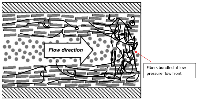
2. The second is the temperature of the flow front of the melt as it moves through the cavity. The graph below shows the temperature of the flow front of the melt.

pressure drop xy molding window


The temperature of the flow front is utilized to determine the best fill speed or fill time. When filling a part, it is recommended to fill at a speed that doesn’t cause the material to shear heat too much or to cool too much due to thermal influences of the tool so the ideal fill speed should be at roughly melt temperature. In the graph above, the best fill speed would be approximately 1.0 second.

In the graph below:

  • The X-axis is the Fill Time. The fill time has been pre-determined via the methods previously stated using the pressure and temperature at flow front graphs.
  • The Y-axis is the Melt Temperature. The melt temperature is also determined using the suggested temperature from the manufacturer combined with the pressure drop in the part.
  • The Z-axis, or cutting plane, is the Mold Temperature. The cutting plane for the mold temperature is adjusted so there is the largest amount of blue ‘preferred’ region. Once the largest mold temperature region is found then the center of the blue region (both left-to-right and top-to-bottom) will also suggest the best fill time and melt temperature.

Molding window zone plot

Once each of the factors are identified, then a virtual analysis is run on the part utilizing these set points. The analysis is then interrogated to see if there are any outstanding issues which may warrant a change of any parameter or factor. A virtual molding window has now been determined for this particular part. The larger this window is, the more variation can occur in the process without losing part quality.

The industry is pushing the limits on plastic part design with regards to complexity and thickness. Material manufacturers are adjusting their materials in order to accommodate the demands of these part design changes. It has become more important than ever to perform a virtual process molding window that is large enough to be robust and create consistently good parts. This process can even vet out parts that cannot be molded.

For more information, support with your Tool Design, assistance Troubleshooting any of your Plastics Injection Molded projects, or Autodesk Moldflow Training contact the Team at Bozilla Corporation.

Bozilla Corporation’s Plastics Injection Molding Team has over 20 years of experience analytically and on the floor. We specialize in optimization, consulting, engineering, troubleshooting and Autodesk Moldflow software training. Additionally, our plastics engineers have a full understanding of polymers and how they influence an injection molded part. Your success is our success. Our skilled Team is focused upon meeting the goals and timelines of our customers.

https://www.Bozilla Corporation.com

800-942-0742

Core deflection in plastics injection molding

Core shift is not always obvious or suspected. Recently, Bozilla Corporation was called upon to investigate a part that was warping differently and more than expected. The customer had a flow simulation conducted by a third party and the warpage results did not match the actual part data. Sometimes part warpage does not match the flow simulation and in many cases, it is easily explained. However, after a quick investigation, the underlying cause of the excessive deflection was not easily understood. It was time for our Team to troubleshoot.

(The animations and images presented in this article do not represent the Customers actual part file and is just an example of how core deflection occurs)

Core deflection fill time graph

To begin the investigation, we compared the floor process to the simulation, which is standard operating procedure. They matched fairly well. They are never a perfect match but were very close. We then looked at the part data and tool design then compared it to the data utilized in the flow analysis. The data matched. This was good news because through process of elimination, we were nearing the target.

We then began taking a closer look at the part along with the flow simulation results. We noticed that there were long features extending from the core side of the tool that the polymer had to flow around and down. The features were thin so they did not have cooling in them therefore it was suspected that these long cores were heating up excessively causing the polymer to stress relieve and therefore warp. However, the simulation software accounted for this to some degree and we did not see a trend that suggested the hot core feature was contributing to additional deflection.

Having a long history with examining many polymers and how they behave in varying geometries caused us to take a closer look at the differential pressure within the cavity as it flowed around and along the long core features. We discovered a significant pressure differential that occurred on either side of the core. We also learned that the polymer did not freeze uniformly around that core during the 2nd stage pack process. Having differential pressure and non-uniform freezing threw up a few flags.

Core shift pressure graph

We had to investigate the impact of the differential pressure and non-uniform freezing on these features. We knew it was time for a core-deflection analysis. The customer was fairly confident that the P-20 tool steel was robust enough to resist any core deflection but over the years, we’ve learned that anything is possible when injection molding.

After running the analysis, we discovered that the long core feature actually did deflect! This was good news for us, not-so good news for the customer. We dug a little deeper into the simulation and found that even though the core deflected during the filling phase, it actually moved back to its nominal position. The most critical piece of information is that the majority of the deflection occurred during 2nd stage pack. The pressure distribution combined with the frozen layer variation across the core created a significant pressure increase on one side of the feature. Because the feature was deflecting during the pack phase, the polymer quickly finished freezing and held the core feature in the deflected position. Not good.

The situation of the deflected feature caused a change in part thickness around the feature. The change in thickness also changes the volumetric shrinkage and residual stress within the polymer. These factors are great contributors to deflection. The warpage results of the core-deflection analysis showed the additional deflection. We have now identified the root cause.

The customer was not very pleased with the findings and was a bit concerned about having to redesign the tool or modify the tool with high-strength inserts. We then offered that before making the large expenditure of modifying the tool he could first try to work with the process to reduce the core deflection. He was a bit surprised but eager to hear what we could suggest.

Since the examination determined that the majority of the final core deflection occurred during 2nd stage pack, we suggested reducing the pack pressure and rerun the gate freeze analysis on the floor.

The customer made his adjustments and found that the part was warping a little less and the measured core deflection was reduced by over 30%. While this was not a perfect fix, it allowed the part to meet specification in which case, the customer was delighted.

We didn’t want to burst the customer’s bubble but we had to give him a dose of reality. We had to explain to him that the core shift that is taking place is fatiguing the tool steel and it may break after a significant amount of cycles. We thought he knew this because he wasn’t surprised. He immediately made plans to insert the core feature with a high-strength steel so that he wouldn’t have a failure in the future. This was a great measure to take and we were happy to hear it.

The graph below is a great illustration of how steel and aluminum fatigue. It is obvious that aluminum is not as strong but the important things to point out are that the steel begins to fatigue but eventually reaches a limit and levels off. As compared to Aluminum, the aluminum begins to fatigue and continues on a downward trend and eventually fails. This is critical for anyone to understand cycle limits in tooling when considering both steel and aluminum.

steel and aluminum fatigue graph

The animation below shows the filling pattern of a basic test-tube shape with a long core. It is gated in a typical location but it is not ideal based on the flow as it travels up the length of the core.

Core shift fill time graph

The resulting deflection, shown in the animation below, illustrates how the core deflects. The deflection reaches a maximum during the filling phase but relaxes slightly once the part finishes filling and packing.

core shift displacement graph

As the core deflects, it experiences a tremendous amount of stress. The image below shows exactly how much stress is calculated during the deflection analysis.

Von Mises Stress graph

Many tools in the industry have cores that may have the potential to physically shift or deflect during the filling and packing process. Whether your tool steel is P20, aluminum or 414 stainless steel, core deflection can take place and happen to you and reveal itself in unexpected ways.

For more information, support with your tool design or assistance troubleshooting any of your injection molded issues, contact the Team at Bozilla Corporation.

Bozilla Corporation’s Plastics Injection Molding Team has over 20 years of experience analytically and on the floor. We specialize in optimization, consulting, engineering, troubleshooting and Autodesk Moldflow software training. Additionally, our plastics engineers have a full understanding of polymers and how they influence an injection molded part. Your success is our success. Our skilled Team is focused upon meeting the goals and timelines of our customers.

www.BozillaCorp.com, 800-942-0742, info@BozillaCorp.com

About Bozilla Corporation: https://youtu.be/HIUfzwf1x90

About the Author:

Chris Czeczuga is a Plastics Engineer, Injection molding expert, Military Veteran and the President of Bozilla Corporation. He has proven success with many Fortune 500 companies throughout the injection molding industry. A graduate from UMass Lowell, he is Expert Certified with Autodesk, has 20+ years of field experience, intimate knowledge of injection molding part, tool and feed system design. Bozilla Corporation’s success is built on providing the highest level of injection molding simulation and consulting advice to businesses who have short lead times, require an efficient, cost-effective molding process, and desire to produce a correct part the first time.

Flow Simulation on plastics injection molding machine

I have recently been exposed to multiple articles and discussions regarding the implementation of flow simulation on injection molding machines. This is an intriguing topic which I advocate. Currently, this new combo method is proving difficult to line up the results from the analysis with the actual process on the injection molding machine. In order to successfully utilize this capability on an injection molding machine, several factors must be understood.

For those who have read my previous articles, you may appreciate that I strongly promote having the right person for the right job. In other words, the simulation engineer must have a complete and comprehensive understanding of plastics in order to be able to properly simulate the plastics injection molding process.

My suggestion is to always have a degreed Plastics Engineer with floor experience perform simulations on plastic parts. The reason for this advocation is to ensure that the simulation engineer virtually takes on the role of the process engineer. This makes certain that the simulation will properly emulate the injection molding machine process on the part being molded. Unfortunately, this is not always the case and the articles I have recently read do not touch on this very important factor. A virtual simulation cannot simply be executed, have the results taken to the floor, input into the injection molding machine and expect the molded part to perfectly match the simulation results. It’s not that easy due to many variables which must be considered.

Plastics injection molding optimization

For example, the simulation engineer (with the proper degree and experience) will understand the limitations and boundaries of the intended injection molding machine for that particular simulated part. It is not always necessary to know every specification of the machine and to input that specific data into the simulation. Most machines have a wide variation of capabilities that the simulation engineer will take into consideration. The simulation will then be executed with all of the necessary variables factored in for the injection molding machine, thus maintaining a high degree of accuracy between the simulation and the floor.

The difficult task is discovering those unintended variables that affect the process on the floor, e.g. material batch changes, colorant issues in the polymer, tool temperature variations that the press cannot record, physical changes within the tool such as polymer sticking to action within the tool, cold gates not opening and flowing when desired, cosmetic issues at the gate or within the part and the list goes on.

In order to capture these variables, the process engineer must have a method to identify them, or the machine must have instruments that can identify these variables. Once identified, the variables can be obtained by the simulation engineer or AI in order to make improvements in the process.

At Bozilla Corporation, Our Team provides an educated explanation of the differences between these two positions, Simulation Engineer and Process Technician, and bridges the gap in order to create a unified and successful process with minimal error.

In a world where the implementation of AI is becoming more common, it is critical to have a complete understanding of every phase of the plastic part manufacturing process in order to have a successful outcome. Without this information, the AI code will not be able to learn and make the necessary adjustments.

Contact Bozilla Corporation today and let’s discuss how we can successfully contribute to your project. Bozilla Corporation’s Injection molding Team has over 20 years of experience analytically and on the floor. We specialize in optimization, consulting, engineering, troubleshooting and Autodesk Moldflow software training. Additionally, our plastics engineers have a full understanding of polymers and how they influence an injection molded part. Your success is our success. Our skilled Team is focused upon meeting the goals and timelines of our customers.

images for this article courtesy of Engel

www.BozillaCorp.com, 800-942-0742, info@BozillaCorp.com

About Bozilla Corporation: https://youtu.be/HIUfzwf1x90

About the Author:

Chris Czeczuga is a Plastics Engineer, Injection molding expert, Military Veteran and the President of Bozilla Corporation. He has proven success with many Fortune 500 companies throughout the injection molding industry. A graduate from UMass Lowell, he is Expert Certified with Autodesk, has 20+ years of field experience, intimate knowledge of injection molding part, tool and feed system design. Bozilla Corporation’s success is built on providing the highest level of injection molding simulation and consulting advice to businesses who have short lead times, require an efficient, cost-effective molding process, and desire to produce a correct part the first time.

3D printing vs. plastics injection molding

3D printing has been available for decades. There are several reasons it has only begun to gain traction. In this article, we will explore some reasons why has there been so much interest in 3D printing in recent years and how it compares with injection molding.

3D printing began as a method of creating a prototype part that could be physically observed in form, fit and sometimes even functionality before large cash investments were made in the manufacturing process. The methodology of 3D printing started as a simple layering process with either a liquid or powder polymer-based medium.

In the infancy of 3D printing the quality of the printed item commonly could not be utilized as a production part because it had inherent deficiencies. For example, the quality of the adhered layers of the part were weak, making the part susceptible to breakage. In addition, the part was also very porous and could not be used in applications where porosity was not acceptable. Thus, the market for this technology primarily remained in the pre-production hemisphere. Yet, with the advent of material suppliers creating new polymers and polymer blends, the quality of 3D printed parts has significantly improved. The improvements gained include increased bond strength and decreased porosity.

Bond strength of the layers in 3D printing has increased effectively enough so that parts can actually be used for their intended purpose as long as they meet the mechanical demands of the product.

Unfortunately, the 3D layering process creates ‘weld lines’ (an injection molding term) between layers which is essentially two layers of polymer that meet. The problem with ‘weld lines’ or ‘layers’ is that the polymer sits upon itself and has no way of physically mixing. This lack of mixing doesn’t allow the molecules to intertwine and entangle, creating a strong bond. Thus, the actual layering process has an inherent flaw.

However, additional processes have been employed in order to further strengthen the part such as the inclusion of inserts, fiber in the material, and post printing sintering. These additional processes raise the quality of the part up to a level where it can almost compete with the traditional injection molding process. Unfortunately, the combined time to 3D print a part and the implementation of the post molding process translates into a long cycle time for each part. Manufacturers try to overcome this hurdle by purchasing multiple 3D printers which all print the parts simultaneously. This is an additional expense that must have a primary benefit to provide a good ROI.

Another improvement to 3D Printing is decreased porosity. Material suppliers have been working with polymers and polymer blends which decrease porosity. While the porosity has decreased in the evolution of 3D printing, it still remains as it is a bi-product of the ‘layering’ process. A porous plastic does not have any barrier protection and will allow unwanted materials to enter and flow through the pores rendering it useless in many applications. The combination of layering (weld lines) and porosity results in a part with poor mechanical strength regardless of the quality of the material being used as the substrate.

Nevertheless, an outstanding benefit of 3D printed parts is 3D printing can create features both on and within the part. This attribute is, in most cases, impossible for the injection molding process to produce. This is where 3D printing shines. It is this characteristic that has opened the door to the world of 3D printing. That along with the ability to design something and print it immediately is a big factor. There is no waiting for a mold or tool to be built before parts can be generated.

Conversely, the injection molding process is very different from 3D printing. An injection molding machine screw thoroughly mixes the polymer and then injects the polymer into a mold where the polymer is homogenous, thus creating a part with uniform and high mechanical properties. The weakest regions of an injection molded part are high stress zones and weld line regions. Both can be combatted with the use of pre-molding simulation.

Injection molding does have limitations such as creating complex features within a part that cannot be produced due to tool design limitations. These complex features can be cored out regions of the part or internal geometry that cannot be produced in a one-part design or even a multi-part design. Sometimes the ‘lost core’ method (an older method) can be utilized in injection molding in order to create internal cavities within a part that cannot be tooled. However, tool design has come a long way and many creative techniques can now be utilized to accomplish this task. Not all tool and/or part designers may be aware of these techniques so it is important for them to consider using injection experts such as the team at Bozilla Corporation to evaluate the design.  

3D printing vs. Plastics injection molding

When comparing a 3D printed part to an injection molded part, there are definitive differences that make one process better suited than the other when deciding which process to use for manufacturing. 3D printed parts can make very complex parts but concessions will have to be understood such as material porosity, loss of mechanical properties and long cycle times. Alternatively, traditional injection molding can produce less-complicated parts with quick cycle times that have high durability and better overall properties.

Plastics injection molding optimization


However when utilizing the appropriate simulation expertise, building tools with complicated geometry can bring the injection molding process to the next level. Having a clear understanding of the limitations of each process is critical when deciding which technology to utilize on a project.

Contact Bozilla Corporation today and let’s discuss how we can successfully contribute to your project. Bozilla Corporation’s Injection molding Team has over 20 years of experience analytically and on the floor. We specialize in optimization, consulting, engineering, troubleshooting and Autodesk Moldflow software training. Additionally, our plastics engineers have a full understanding of polymers and how they influence an injection molded part. Your success is our success. Our skilled Team is focused upon meeting the goals and timelines of our customers.

www.BozillaCorp.com, 800-942-0742, info@BozillaCorp.com
About Bozilla Corporation: https://youtu.be/HIUfzwf1x90


About the Author:

Chris Czeczuga is a Plastics Engineer, Injection molding expert, Military Veteran and the President of Bozilla Corporation. He has proven success with many Fortune 500 companies throughout the injection molding industry. A graduate from UMass Lowell, he is Expert Certified with Autodesk, has 20+ years of field experience, intimate knowledge of injection molding part, tool and feed system design. Bozilla Corporation’s success is built on providing the highest level of injection molding simulation and consulting advice to businesses who have short lead times, require an efficient, cost-effective molding process, and desire to produce a correct part the first time.


Impact of Fiber orientation on part quality and deflection


For Plastics Injection Molding, the addition of glass or carbon fiber into a polymer is initiated to typically strengthen and increase stiffness in a part. There are significant factors that must be considered when fiber is added that will have an impact on part quality and deflection.

These include:

  • Material viscosity
  • Material type (i.e. crystalline, amorphous or semi-crystalline)
  • Part design
  • Process conditions (filling rates, melt and mold temperatures and pack pressure).

Adding fiber to a material is not so simple. It is very important to understand the characteristics and behaviors of that material and adding fiber will dramatically influence these factors. Fiber has orientation characteristics which will impact the performance of the part. Having the material tested or acquiring the test data will provide a better understanding of how the material will perform.

Why is fiber orientation important? Orientation of the fiber can provide increased properties when it is highly and consistently oriented, which is typically in the direction of flow. Conversely, the properties are at a much lower transverse to the direction of flow. Similarly, the shrinkage characteristics are also impacted by fiber orientation. The polymer will shrink less in the direction of flow (parallel) and more transverse (perpendicular) to flow. This variation will cause a part to warp. Below is an image showing the shrinkage properties of a 30% glass filled polypropylene.

Shrinkage observed plastics injection molding

Notice that the observed nominal shrinkage in the direction parallel to flow was 0.1530% and 0.7741% in the direction perpendicular to the direction of flow. That’s 5 times more shrinkage in the direction perpendicular to flow.  This variation within the part is what causes part warpage and deflection.

In order to have a better understanding of the factors that impact fiber distribution, we will discuss how fiber orients within the cross-section of a part.

Fiber orientation within the part cross-section is critical with regards to consistent and uniform (isotropic) properties within the part. The use of fiber will offer the greatest strength if the fiber is oriented uniformly within the entire part. However, with regards to the flow characteristics of a polymer within the geometry of the part, there are many regions where the flow patterns cause the fiber to be less oriented or more random. These regions will have less strength. Furthermore, weld lines within the part will be very weak. A weld line that forms and does not continue to be pushed, yet flows, downstream will also be weaker than a weld line that does get pushed downstream. When a weld line forms, it will have a considerable amount of fiber at the head of each flow front that will abut against each other and not mix.   This is due to the lower density glass fiber migrating to the head of the flow creating a ‘bundle’ of fiber that meets at the weld line location. This bundle of fiber displaces the polymer yielding a weld line with very poor mechanical strength. Without the necessary polymer molecule to intertwine, the resulting weld line is prone to being weaker than the same resin without glass fiber.   If the weld line initially forms then gets pushed further downstream, the glass fibers will then get dispersed creating a higher strength zone. Below is an image showing the orientation at the weld line locations. Notice how the simulation result shows the fibers are randomly oriented at the weld line locations (blue lines).

Flow with glass orientation


The viscosity of the material can have a large influence on the behavior of glass fiber distribution. As mentioned previously, due to the inherent density variation between the fiber and the polymer, the glass fiber has the tendency to be pushed to the head of the flow front due to the pressure gradient within the polymer. A lower viscosity material such as a PA6/6, as compared to polycarbonate, will allow the glass fiber to move more readily within the polymer and migrate to the head of the flow front quicker and easier.  This is commonly seen in round parts such as gears with spokes where the flow front will propagate outward in the spokes and as the flow front meets around the perimeter of the part, the glass fiber is abundant and the weld lines that form are poor due the lack of base resin coupled with the high content of randomly oriented fiber.

The filling rate can have a significant impact on glass fiber orientation. When the filling rate is increased, the fibers will have a higher degree of orientation within the part cross-section.  If the filling rate is too fast, the stress on the fibers can cause the fibers to break therefore decreasing the strength of the overall part.

The cross section is also critical with regards to fiber orientation. If the part cross-section decreases then the velocity profile will increase and therefore create a higher degree of glass alignment in that region. If the cross section increases then the velocity will decrease and there will be a higher degree of random orientation as seen below.

fiber cross section

The nature of the polymer and how it shrinks will depend on the 2nd stage of the molding cycle, pack stage. 

The pack stage is important because we want to minimize the shrinkage effects of the polymer on the deflection of the part. Remember that the shrinkage of a fiber filled polymer is greater in the transverse direction of flow. The shrinkage can be kept to a minimum by ensuring enough pack pressure is used, providing enough pack time.

Since material shrink is critical, the type of polymer will also have an impact when using fiber. A crystalline material will shrink more than a semi-crystalline material, which will shrink more than an amorphous material. The shrinkage characteristics of each type of material will have an impact with regards to fiber orientation.

While the incorporation of fiber into a polymer can generally improve part properties, it can also cause potential issues such as weak weld lines and undesirable part deflection. Material type, viscosity, part design and processing can all contribute to the outcome of the quality of the part when using fiber fillers. Understanding the combined  factors’ influence on the part is challenging. It is highly recommended that a flow analysis be conducted in order to identify how these factors it will affect the part you are creating.

Contact Bozilla Corporation today and let’s discuss how we can successfully contribute to your project. Bozilla Corporation’s Injection molding Team has over 20 years of experience analytically and on the floor. We specialize in optimization, consulting, engineering, troubleshooting and Autodesk Moldflow software training. Additionally, our plastics engineers have a full understanding of polymers and how they influence an injection molded part. Your success is our success. Our skilled Team is focused upon meeting the goals and timelines of our customers.

www.BozillaCorp.com, 800-942-0742, info@BozillaCorp.com

About Bozilla Corporation: https://youtu.be/HIUfzwf1x90

About the Author:

Chris Czeczuga is a Plastics Engineer, Injection molding expert, Military Veteran and the President of Bozilla Corporation. He has proven success with many Fortune 500 companies throughout the injection molding industry. A graduate from UMass Lowell, he is Expert Certified with Autodesk, has 20+ years of field experience, intimate knowledge of injection molding part, tool and feed system design. Bozilla Corporation’s success is built on providing the highest level of injection molding simulation and consulting advice to businesses who have short lead times, require an efficient, cost-effective molding process, and desire to produce a correct part the first time.

Cold sprue vs. Hot Runner Technology

With the advancements in feed system technology, when is it truly practical to design a cold sprue into a part or feed system? Before we answer this question, the purpose of the cold sprue must be considered.

The cold sprue is simply a means to get polymer from the injection molding machine to the cavity (or at least that’s how it was in ‘the beginning’).  However, cold sprues are typically large, which leads to waste, and are typically thick, which may contribute to long cycle times.

With the advancement of feed system technology, there are additional and potentially more efficient ways of transferring polymer from the machine to the cavity. However, costs will need to be considered.

Designing a Cold Sprue into a Part

Cold Sprue


Considerations when designing a part with a cold sprue include:

  1. Wall thickness: If the cold sprue is designed to drop directly onto the part, the nominal wall thickness of the part must be considered. The nominal part thickness will dictate the size the diameter sprue should be on the part (or at least it should) based on sink marks and freeze times.
  2. Properly sized: If the cold sprue drops onto a cold runner which then feeds the part, the cold sprue must be sized such that both the cold runner and cold sprue are not so large that they control cycle time. On the other side of the spectrum, they must not be too small as to create a severe pressure loss and also allow for sufficient pack times to allow the gate to freeze AFTER the part freezes.
  3. Flow Path: The longest flow path (distance) of the polymer as it flows through the cavity.  The flow path must be as short as possible and balanced within the part. It will also depend on the material being used. Some materials can flow much further than others.
  4. Sink Marks: Account for possible sink marks in the part design on the opposite side of the cold sprue. Sometimes a small mound may be required to be designed onto the part opposite the cold sprue to prevent excessive shear which may cause visual defects such as splay. However, a thick region on the part may lead to a sink mark. If there is potential for a sink mark on the part opposite the sprue, it may even be necessary to model in a small dimple opposite the sprue.
  5. Removal of Sprue: Removing a cold sprue after ejection is an additional process and has associated costs.
  6. Proper Design: The sprue will also need to be designed so that sharp edges at the base of the sprue where it meets the part are relieved with sufficient radii to prevent the polymer from shearing as it enters the part, which could cause surface defects on the part.
  7. Location of Sprue: The sprue location is typically dictated by the part as it lies in tool position.  However, as mentioned in line 3, the    sprue must be placed in a balanced location on the part. If the part does not fill in a balanced fashion, it could lead to potential flash, cantilevering of the tool, actions in the tool sticking and many other potential processing issues.

Shear zone for an injection molded part

Part Design

With the demand for thinner, more complicated parts, it may be necessary to have multiple gate locations on the part to fill the part completely.

There are ways to determine if one sprue is sufficient is to fill the part based on the flow length. 

  • Flow length, i.e. ‘distance – to- part thickness’ ratio which is material dependent. Some materials can flow much further than others.
  •  Identify the temperature loss across the part as it is being filled. It is important to maintain a certain temperature across the part.
  • The pressure to fill the part is also very important. High fill pressures can lead to stress within the part which can lead to warpage. High fill pressures can also place undo wear on the injection molding machine as well as high clamp force.

From a design perspective, it may seem best to simply place the cold sprue in the center of the part based on the parts location in tool position. This can potentially lead to many issues based on the aforementioned considerations.

Without the use of analytical tools, it’s difficult to prove that a part will not be optimally designed if a single, cold sprue is used. However, it’s often proved that it wasn’t the best design after the part was made. It’s old technology and only has a place in very specific conditions.

Hot Runner Technology

With the advances made in hot feed systems, it can sometimes be more cost effective to employ the use of hot runner technology.

sprue bushing


With the use of a hot sprue bushing, polymer can be taken directly from the machine nozzle and fed directly onto a part or a cold runner.  The sprue bushing both eliminates scrap and post-process trimming if applicable.  Naturally, eliminating scrap is an automatic cost savings. Many times, scrap cannot be re-used and it is not cost effective.

nozzel for hot drops

Hot drops (both thermal and valve gates) allow many drop locations to be considered for a part based on the requirements of the part design and material being considered.

There are quite a few options with regards to hot runner technology but price and application will need to be considered.

Hot runners can also employ the use of cold sprues. In some cases it is necessary to utilize a cold sprue on the tip of a hot drop because a hot drop may fall onto a part surface with a steep angle, therefore a cold sprue must be designed into the drop tip. Even so, technology now permits hot drops to be designed at an angle so that a cold sprue is no longer required.

In conclusion, sometimes it is practical to design a cold sprue onto a part but there are many factors to consider. Hot runner technology allows for additional options which may incorporate the use of cold sprues.  Typically, a flow analysis will help determine which application is best.

Contact Bozilla Corporation today and let’s discuss how we can successfully contribute to your project.

www.BozillaCorp.com, 800-942-0742, info@BozillaCorp.com

Bozilla Corporation’s Injection molding Team has over 20 years of experience analytically and on the floor. We specialize in optimization, consulting, engineering, troubleshooting and Autodesk Moldflow software training. Additionally, our plastics engineers have a full understanding of polymers and how they influence an injection molded part. Your success is our success. Our skilled Team is focused upon meeting the goals and timelines of our customers.

About the Author:

Chris Czeczuga is a Plastics Engineer, Injection molding expert, Military Veteran and the President of Bozilla Corporation. He has proven success with many Fortune 500 companies throughout the injection molding industry. A graduate from UMass Lowell, he is Expert Certified with Autodesk, has 20+ years of field experience, intimate knowledge of injection molding part, tool and feed system design. Bozilla Corporation’s success is built on providing the highest level of injection molding simulation and consulting advice to businesses who have short lead times, require an efficient, cost-effective molding process, and desire to produce a correct part the first time.


Injection Molding Simulation Report

I have written in a prior post about the key factors necessary in a plastics injection molding optimization analyst.  Now, I would like to discuss the importance of a skillfully assembled simulation report.  Jennifer Schmidt spoke of the key ingredients of a trustworthy injection molding simulation report in her talk at the Plastics Technology Molding 2021 conference. In this brief, I will discuss the valuable information she provided and add additional feedback.  If you want a successful outcome for your tool, these key components are essential to consider.


Injection Molding simulation software

1.Software

  • What version is being used and is the software up to date? Look for signs that the analyst is using an older version of software which will alter the results on the report, and ultimately the floor results.

Typically, the output file(s) of the software contain the release version of the software.  It might not be the absolute latest release of the software, but is should be a proven release which is typically a year old or less.

Mesh quality for injection molding

2. Type of Mesh used: Consider the type of mesh that used for the part and the runner.

  • Is the mesh type appropriate for the part geometry?
  • Is it precise enough in critical areas to capture important details?
  • Is the correct technology being used for the part geometry/runner combination, i.e. midplane, Dual-Domain, 3D or a specialty mesh used?
  • Will the report allow access to display the mesh?
  • Does the filling animation, weld lines and sink marks reveal insights into the mesh quality?

Consider: Simulations of the same part with the same material and same mesh density, but different mesh types for the part and runner, may produce different results for pressure at the fill-to-pack switchover point, which could make quite a difference in what occurs in an actual molding environment.

There are many factors to consider and only a seasoned user with the proper education in the software will be able to make these determinations in order to provide the best analytical outcome.

Material Data for injection molding


3. Material Data: An accurate molding prediction requires good material data.

  • What was the material data in the simulation based on?
  • Was data on the actual material available?
  • Was the data a substitute?-a resin of the same generic family but has a different molecular weight, flow characteristics, and different level of fillers, reinforcements or other additives used in the actual molding?
  • What was the level of material characterization? How much data was available? How recently was that data generated? Has the formulation changed?

There are many ways for the material data to be manipulated.  It is critical that the user understand the data and how to identify if the data has been changed to suit the needs of the project.  Unless the user is skilled in material data characterization, changing any component of the material data can be very dangerous as it will affect the outcome of the simulation.

4. Credibility of predictions:

  • What was modeled?
  • What analysis sequences were run?
  • Are there inputs for the results that can be reviewed?
  • Is there data on time to freeze, volumetric shrinkage, cooling, etc?

There are many criteria to consider with regards to credibility.  The analyst must have a clear understanding of the objective of the project so the analytical approach addresses the concerns and outcome of the project.

Credibility of predictions in injection molding


5. Processing Conditions- Beware of default settings

  • What processing conditions were used?- fill time, mold temp, melt temp, packing pressure, packing time, cooling?
  • How were the processing conditions determined?

It is rare that the default settings apply to any project.  There are a host of settings that must be addressed in order to have an accurate prediction.  Default settings can actually cause the software predictions to be less accurate.

Is your injection molding analyst qualified?

6. The Analyst: Who is the Analyst?

  • Are they certified, experienced, knowledgeable about the Software? Polymers? Processing Conditions?
  • What is the level of their experience or plastics background?
  • How often do they perform similar simulations?

The skillset of the analyst is probably the most important factor with regards to the usage of plastics injection molding analytical software.  Simulation software requires knowledge in polymers, chemistry, metallurgy, part design, tool design, injection molding processing, design of experiments (DOE), heat transfer, just to name a few.  Any information that the analysis does not know will detract from the overall quality and outcome of the project.  When creating a simulation report, having a skilled, knowledgeable and qualified analyst is the key component that will produce the desired result for your project.

Molding simulation has changed the culture of injection molding by saving time and money on ‘trial and error’ mold development and rework. However, it is necessary to have skilled professionals accurately manage the software and interpret results with a critical eye.

Bozilla Corporation’s Injection molding Team has over 20 years of experience analytically and on the floor.  We specialize in optimization, consulting, engineering, troubleshooting and Autodesk Moldflow Training. Additionally, our plastics engineers have a full understanding of polymers and how they influence an injection molded part. Your success is our success and we focus on meeting the goals and timelines of our customers.

Contact Bozilla Corporation today and let’s discuss how we can successfully contribute to your project!

www.BozillaCorp.com, 800-942-0742, info@BozillaCorp.com


injection molding clamp force

To start this discussion I’d have to first state that the size of the tool plays a large role when selecting an injection molding machine.  More specifically, it is the projected area that is of concern and how the projected area, along with the pressure distribution over that projected area, creates clamp force.

Selecting a machine based on clamp force (tonnage) is more common when you have a part with a large projected area; i.e. multi-cavity tools, bumper fascias, housewares and many other items.

In today’s economic climate, it’s more important than ever to conserve energy.  Many believe that using the smallest IMM is the best way to achieve this cost savings.  However, there are reasons why a smaller machine isn’t always the most efficient machine.

 Reason 1: If an optimum process is the objective, select a machine that does not allow the tool to exceed the clamp force and flash the tool (blowing open)  during an  ‘optimized’ process.

We  have had many concerned customers consult with us about the process. Their questions are directed at finding out why the part is warping or exhibiting cosmetic defects.  Once I dig into the process, I typically find that the part is not packed sufficiently due to the tool blowing open.  In order to keep the tool closed, they must pack with very little pressure for a very short time.  Packing with too little pressure, too little time, or both can cause a loss of control with dimensional stability and/or cosmetic issues due to excessive shrinkage.  These issues create problems that are caused because the tool is in an IMM that doesn’t have the proper clamp force requirement.

In the image below the clamp force required to fill and make the part is 250 Tons.  However, in order to pack the part out sufficiently and make a good part (meets tolerances, minimal cosmetic defects, minimal deflection, etc.) the clamp force required during 2nd stage pack is 1,450 Tons.  That’s a very big difference.

clamp force plot


 Reason 2: You are able to make parts but the process window is so small that staying within the process window is difficult or impossible to maintain.

The inability to stay within a process window could be caused by several issues, especially since there are so many variables in the molding process.  However, if the machine does not have sufficient clamp force to stay closed during an optimum molding process, concessions will be made and you may find yourself on the edge or on the outside of the molding window. For example, in order to keep the clamp closed, the process may need to be pressure limited.  Limiting the pressure can prevent the part from being filled and/or packed sufficiently. Once this happens, its very difficult to find a molding window for the duration of production for that tool.  Utilizing a process that does not have a proper molding window proves inefficient with regards to waste, lost productivity, lost man hours, excessive energy consumption, etc.

Reason 3: Valve gates (if applicable) are closed prematurely during 2nd stage to prevent the clamp from blowing open.

Here is a common practice that often ends in poor part production.  Valve gates are not as simple as many often think.  When valve gates are sequenced, the 1st stage injection velocity must be profiled to accommodate the extra valve gates opening.   Similarly, during 2nd stage, the valve gates must remain open until the part freezes up to the gate (very near the gate but not on the gate).  If any valve gate is closed before the part freezes, the chances of having backflow increases dramatically.  Backflow is a condition where material either changes direction or stops then starts again.  Both backflow situations can cause tremendous stress and could produce a fracture between laminae within the part.  Furthermore, the part will not be packed in the region of the valve gate that has been closed.  The underpacked region will shrink excessively potentially losing mold surface texture, rippling, sink or a host of other cosmetic issues.  A part that is not packed sufficiently is susceptible to high volumetric shrinkage which is a precursor to warpage.

 Reason 4: The reject rate is high leading to lost revenue

A high reject rate may be due to the inability to stay within the optimum molding window resulting in a ‘floating’ process that changes because of any slight variation.  The inability to stay within a molding window may be due to the clamp force controlling the process rather than the process settings controlling the process. High injection rates costs valuable time, money and resources.

In conclusion, it is more crucial than ever to specify an injection molding machine (IMM) worthy of the process required for that part, especially parts with a large projected area.  This is not a simple hand calculation based on the type of resin used (X Tons of clamp force per square inch based on a specific type of resin).  It becomes more complicated than that and is typically a function of the pressure distribution over the projected area during 2nd stage pack.

So how do you know what the required clamp force will be for your part?  A flow analysis will provide the answer.

The Team at Bozilla Corporation are plastics engineers with over 20+ years of analytical and floor experience. We can perform a flow analysis and consult with you to ensure you are making the best choice for selecting an appropriate sized Injection Molding Machine for your project. Contact us today and let’s get started!

www.BozillaCorp.com– Injection Molding Specialists- engineering, consulting, optimization, failure diagnosis, training

About the Author

Chris Czeczuga is a Plastics Engineer, Injection molding expert, Military Veteran and the President of Bozilla Corporation. He has proven success with many OEM’s, Tier 1’s, Tier 2’s, Tool Shops, Molding Shops, Part Designers, Processors and Fortune 500 companies throughout the injection molding industry. A graduate from UMass Lowell, he is Expert Certified with Autodesk, has 20+ years of field experience, intimate knowledge of injection molding part, tool and feed system design. Bozilla Corporation’s success is built on providing the highest level of injection molding simulation and consulting advice to businesses who have short lead times, require an efficient, cost-effective molding process, and desire to produce a correct part before mold steel is cut.


valve gates and sequencing

Valve Gates are invaluable as they relate to their primary design purpose and have many important functions.

 They can:

✔ Eliminate waste that cold runners create

✔ Eliminate vestige

✔ Be sequenced

✔ Eliminate weld lines

✔ Control filling patterns

However, users should be aware that there are a few potential issues that could come with using valve gates and sequencing.

valve gates for injection molding

 Vestige v. Witness Marks

Valve gates can minimize or completely remove vestige by direct gating on the part.  They do leave witness marks on the part where the valve gate tip seats into the cavity but with proper grinding or surface finish, it can be minimized or completely hidden.

 Controlling the Fill Pattern v. Machine Stroke Programming

When multiple valve gates are used to fill a part, it may be necessary to time the sequencing in order to create a more uniform filling pattern.  It is extremely important to understand that if the valve gates are sequenced, then the flow rate input must also match the demand of the feed system.

For example: If your tool has four valve gates and you initially open two valve gates, then open the next two valve gates, the IM machine must deliver twice the flow rate when the two additional valve gates are opened in order to maintain equal flow rates through all nozzles in the feed system.

If the machine stroke is not profiled to compensate for the flow rate demand, the properties of the polymer will change in the cavity due to different filling rates.  This could translate into non-uniform shrinkage and stress which directly translates into warpage.  It can also cause surface finish variations as shown in the picture below.

Nozzle and machine pressure for injection molding

Cascade Sequencing (eliminate weld lines) v. Machine Stroke Programming

If the intention is to sequence the valve gates as the flow front passes by in order to remove weld lines, then the same concerns arise if the machine stroke is not programmed to compensate for the additional flow rate demand as additional nozzles are opened.

Cascade sequencing can also create back-flow and uneven packing along with uneven stress even if the machine stroke is profiled to compensate for flow rate.

Cascade sequencing removes weld lines, therefore the potential problems that accompany it must be weighed.  Cascade sequencing should be used as a last resort when trying to eliminate weld lines.

Valve Pin Control

Hot runner manufacturers have now developed controllers to move the valve pin at a specified rate.   This allows the user to open the valve pin slowly which prevents the sudden burst of polymer into the cavity thus preventing the sudden loss of pressure in the feed system which causes hesitation in other regions of the cavity.  This is an extremely useful implementation but does come at a cost and can be tricky to set up.

Conclusion

Even though valve gates can aid in creating parts with little or no vestige, they have other purposes that can help the molding process.  These other purposes can come with implications which can instigate problems if not considered.

The use of FEA (Mold filling analyses) can be used to take full advantage of valve gate sequencing.  It can also address most, if not all, of the potential issues that can occur from the use of valve gate sequencing.  Without the use of such tools, the potential for complication is fairly high.  To limit difficulties and setbacks, contact an injection molding professional who will offer solutions and feedback to avoid or correct issues that arise.

www.BozillaCorp.com

We Know Injection Molding! Plastics Engineering, Consulting, Optimization, Failure Diagnosis, Training

About the author

Chris Czeczuga is a Plastics Engineer, Injection molding expert, Military Veteran and the President of Bozilla Corporation. He has proven success with many OEM’s Tier 1’s, Tier 2’s, Tool Shops, Molding shops, Part Designers, Processors and Fortune 500 companies throughout the injection molding industry. A graduate from UMass Lowell, he is Expert Certified with Autodesk, has 20+ years of field experience, intimate knowledge of injection molding part, tool and feed system design. Bozilla Corporation’s success is built on providing the highest level of injection molding simulation and consulting advice to businesses who have short lead times, require an efficient, cost-effective molding process, and desire to produce a correct part before mold steel is cut.

causes of warpage in plastics injection molding

Based on part geometry, gate location(s) will determine how the polymer fills the cavity.  If the cavity doesn’t fill in a balanced/uniform fashion, the internal stresses will be anisotropic- meaning non-uniform properties.  So it is important to place a gate in a location such that the polymer flowfront fills the cavity at a uniform rate and reaches the end of the cavity at all locations, including weld line locations, simultaneously.

With simple part geometry, identifying an ideal gate location may be possible by using experience and examining the part.  However, with more complex geometry and gating limitations (cooling line interference, ejector pin interference, slides, etc.), it is nearly impossible to determine the appropriate gate location(s) without using FEA(flow simulation).  Not only can FEA(flow simulation) produce actual deflection results(warpage), it can also provide data that is a precursor to warpage-such as volumetric shrinkage and frozen-in stress which is typically due to a response from forcing the material into the cavity while the material is trying to freeze.

gate location and part warpage courtesy of sciencedirect.com

Gate location(s) will determine polymer orientation.  Based on that location, it will ultimately determine polymer shrinkage.  Also, different regions of the part will cool at different rates(regions of the cavity near the gate that were first to fill will cool before regions furthest from the gate).


Why is this important?  Because there are 3 major components that contribute to warpage:

 Polymer Orientation

Polymer Shrinkage

Cooling Effects


Shrinkage and orientation are both directly correlated to injection location(s) on a part as it relates to processing conditions.  Warpage due to cooling effects is  based on the rate of how the polymer cools on one side of the cavity relative to the other side. Non-uniform cooling through the thickness will create warpage.

Because gate location(s) directly correlates to the contributors of warpage, gate location is therefore extremely important in the tool creation process and ultimately the quality of the part.

The injection molding professionals at Bozilla Corporation have over 20 years of experience assisting OEM’s, Tier 1 & Tier 2 suppliers, and Tool Shops to create quality parts that meet timing and goals.

www.BozillaCorp.com


About the author

Chris Czeczuga President Bozilla Corporation

Chris Czeczuga is a Plastics Engineer, Injection molding expert, Military Veteran and the President of Bozilla Corporation. He has proven success with many OEM’s Tier 1’s, Tier 2’s, Tool Shops, Molding shops, Part Designers, Processors and Fortune 500 companies throughout the injection molding industry. A graduate from UMass Lowell, he is Expert Certified with Autodesk, has 20+ years of field experience, intimate knowledge of injection molding part, tool and feed system design. Bozilla Corporation’s success is built on providing the highest level of injection molding simulation and consulting advice to businesses who have short lead times, require an efficient, cost-effective molding process, and desire to produce a correct part before mold steel is cut.