Tag: polymer

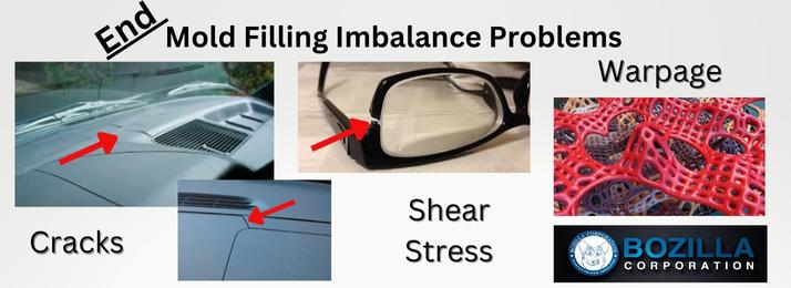
End Part Failure due to Mold Filling Imbalance

By Bozilla
June 7, 2023

Is Part quality and performance of your injection molded part important? Do you enjoy spending that extra time and money having your tool reworked? How about the pleasure of explaining the faulty part to your OEM? Let’s get real Balance your tool analytically before mold steel is cut-NO EXCEPTIONS! If you ignore this step, there is a decent chance of experiencing an unfavorable result on complex or seemingly simple tools

Let’s discuss mold balance

When can a mold-filling imbalance occur? These imbalances may be due to gate location(s) on the part, part geometry, or a combination of both Unless it is analyzed in flow simulation software, it is extremely challenging to determine how a part will fill

What creates an imbalance?

In a single cavity tool, an imbalance can occur when one location of the cavity finishes filling while another has yet to fill

In a multi-cavity tool and family tool, the same imbalance may occur within each cavity, but an imbalance may also arise from cavity to cavity

 How can imbalances cause problems with part quality and performance? 

 It is crucial to understand polymer flow A plastic engineer excels at possessing polymer knowledge Applying this expertise during the virtual optimization stage of your injection molded part will provide significant insight into an imbalance, which can affect part quality and performance

Where can an imbalance occur?

As the cavity fills, the temperature of the polymer flowing through the tool must not fluctuate to keep the properties of the polymer consistent throughout the cavity If flow velocity isn’t uniform in any region of the cavity, hesitation can occur and cause the polymer to cool down As the polymer cools, a frozen layer will form on the mold walls This frozen layer forms more rapidly in slower-moving regions and exceptionally fast in areas where the flow has stopped Once the cavity produces enough pressure to continue filling these hesitating regions, the flow will begin to move again However, the polymer is now cooler and will create tremendous shear stress as it continues to fill the remainder of the cavity THIS SHEAR STRESS WILL CREATE THE POTENTIAL FOR PART DEFLECTION AND EVEN PART FAILURE

If imbalances occur in a multi or family tool, the entire cavity experiencing the hesitation is at risk for this increased shear stress The imbalance also causes the hesitating region of the cavity to become non-uniformly packed, which translates into non-uniform shrinkage, another precursor to part warpage

shear in polymer

How does

Read More

Is Using MFR the Best method for Material Selection?

By Bozilla
December 1, 2022

When a material selection comes down to flow rate, is using the (Mass Flow Rate) MFR or Melt Index (MI) the best choice? To answer this, we need to understand why the Melt Index test initially came about

The Origin of the Melt Index Test Method (ASTM D-1238)

ASTM D 1238: Test Method for Flow Rates of Thermoplastics by Extrusion Plastometer

Before there were standards to test polymers, there was a need to determine the differences in how polymers would flow when melted A method was created to keep all polymers on the same level playing field This method places the material in an Extrusion Plastometer or Melt Indexer

furnace of the plastometer and extrusion plastometer

The standard has the barrel of the melt indexer heated to a specific temperature The user would obtain a resin sample and place it in the barrel where a piston would be inserted A specific load would be placed on the piston, and the melted polymer would be extruded through a capillary die (with a particular orifice size) The extrusion would take place for 10 minutes, and the amount of polymer would be weighed in grams yielding an output in g/10 minutes

Having MFR data for all materials allows one to compare them side-by-side, giving a respective idea of how each will flow with the other

The limitation of this test method is that it is, in fact, one point on the viscosity curve and is at a shear rate of nearly zero, which is not indicative of the injection molding process

When materials experience shear during injection molding, shear rates may be experienced up to and possibly exceeding 100,000 1/sec Some materials become more viscous at higher shear rates, but these are uncommon

So how do we compare materials at these higher shear rates?

Since the inception of the melt indexer (1950s), a much more accurate test method was designed using a Dual Capillary Rheometer

Dual capillary rheometer

A dual capillary rheometer can produce a series of viscosity data points over a range of shear rates, such as the image below

rheology curve

A Rheology curve provides exact viscosity data based on specific shear rates at specifically tested temperatures Notice how the Melt Index MFR point does not provide any data relating to the injection molding process A curve like this will allow one to understand the exact behavior of the material and shear rate

Read More

Homopolymer vs. Copolymer

By Bozilla
May 24, 2022

Material selection for an injection molding application can sometimes prove to be very challenging What happens if you identify a material then find that it can be supplied as a homopolymer or a random copolymer Is there a difference? The answer is YES The choice made for your project can affect part quality  

The Homopolymer:

homopolymer chain

A homopolymer has the same base unit which causes the molecular chain to have a high degree of consistency and size However, length can vary depending on how long the polymerization process is allowed to occur

The high degree of consistency in a homopolymer creates a high degree of regularity When many of these changes flow and combine, they are able to create a very tight entanglement and when they cool and shrink, they also have a high degree of crystallinity which increases shrink

The Copolymer:

copolymer chain

A copolymer, as shown in the image above, has more than one base unit and each base unit is a different size There can be more than two base units Due to the variation in size of the base units, the copolymer chains will be spaced much further from each other and have a higher degree of irregularity And similar to the homopolymer, the length of the molecule will depend on how long the polymerization process is allowed to occur

The high degree of irregularity does not allow the polymer chains to form a tight structure, leaving a lot of space between the molecular chains Therefore, when the polymer flows, there can be alignment but there will be more irregularity and not as tight of a structure which prevents excessive shrinkage

When comparing the two types of polymers, assuming each is the same length (same molecular weight, per se) the homopolymer will be much more organized and structured therefore creating more mechanical strength and chemical resistance but have high shrinkage The copolymer will have more random orientation which will create space between the molecules allowing for easier chemical attack and less mechanical strength and also have lower shrinkage Of course, we could discuss these comparisons in much more detail but we will stick to the basics for now

As material selection relates to injection molding, the properties of the material is a crucial factor

The major properties when comparing homopolymers to copolymers are:

  • shrinkage
  • chemical resistance
  • mechanical strength

Each of these properties must be considered with regards to the outcome of part quality

For example, when injection molding

Read More

Can Gate Location Really affect Part Warpage?

By Bozilla
August 17, 2021

Based on part geometry, gate location(s) will determine how the polymer fills the cavity  If the cavity doesn’t fill in a balanced/uniform fashion, the internal stresses will be anisotropic- meaning non-uniform properties  So it is important to place a gate in a location such that the polymer flowfront fills the cavity at a uniform rate and reaches the end of the cavity at all locations, including weld line locations, simultaneously

With simple part geometry, identifying an ideal gate location may be possible by using experience and examining the part  However, with more complex geometry and gating limitations (cooling line interference, ejector pin interference, slides, etc), it is nearly impossible to determine the appropriate gate location(s) without using FEA(flow simulation)  Not only can FEA(flow simulation) produce actual deflection results(warpage), it can also provide data that is a precursor to warpage-such as volumetric shrinkage and frozen-in stress which is typically due to a response from forcing the material into the cavity while the material is trying to freeze

gate location and part warpage courtesy of sciencedirectcom

Gate location(s) will determine polymer orientation  Based on that location, it will ultimately determine polymer shrinkage  Also, different regions of the part will cool at different rates(regions of the cavity near the gate that were first to fill will cool before regions furthest from the gate)


Why is this important?  Because there are 3 major components that contribute to warpage:

 Polymer Orientation

Polymer Shrinkage

Cooling Effects


Shrinkage and orientation are both directly correlated to injection location(s) on a part as it relates to processing conditions  Warpage due to cooling effects is  based on the rate of how the polymer cools on one side of the cavity relative to the other side Non-uniform cooling through the thickness will create warpage

Because gate location(s) directly correlates to the contributors of warpage, gate location is therefore extremely important in the tool creation process and ultimately the quality of the part

The injection molding professionals at Bozilla Corporation have over 20 years of experience assisting OEM’s, Tier 1 & Tier 2 suppliers, and Tool Shops to create quality parts that meet timing and goals

wwwBozillaCorpcom


About the author

Chris Czeczuga President Bozilla Corporation

Chris Czeczuga is a Plastics Engineer, Injection molding expert, Military Veteran and the President of Bozilla Corporation He has proven success with many OEM’s Tier

Read More