Tag: Injection Molding

Valve Gates and Sequencing-for injection molding

By Bozilla
August 24, 2021

Valve Gates are invaluable as they relate to their primary design purpose and have many important functions

 They can:

✔ Eliminate waste that cold runners create

✔ Eliminate vestige

✔ Be sequenced

✔ Eliminate weld lines

✔ Control filling patterns

However, users should be aware that there are a few potential issues that could come with using valve gates and sequencing

valve gates for injection molding

 Vestige v Witness Marks

Valve gates can minimize or completely remove vestige by direct gating on the part  They do leave witness marks on the part where the valve gate tip seats into the cavity but with proper grinding or surface finish, it can be minimized or completely hidden

 Controlling the Fill Pattern v Machine Stroke Programming

When multiple valve gates are used to fill a part, it may be necessary to time the sequencing in order to create a more uniform filling pattern  It is extremely important to understand that if the valve gates are sequenced, then the flow rate input must also match the demand of the feed system

For example: If your tool has four valve gates and you initially open two valve gates, then open the next two valve gates, the IM machine must deliver twice the flow rate when the two additional valve gates are opened in order to maintain equal flow rates through all nozzles in the feed system

If the machine stroke is not profiled to compensate for the flow rate demand, the properties of the polymer will change in the cavity due to different filling rates  This could translate into non-uniform shrinkage and stress which directly translates into warpage  It can also cause surface finish variations as shown in the picture below

Nozzle and machine pressure for injection molding

Cascade Sequencing (eliminate weld lines) v Machine Stroke Programming

If the intention is to sequence the valve gates as the flow front passes by in order to remove weld lines, then the same concerns arise if the machine stroke is not programmed to compensate for the additional flow rate demand as additional nozzles are opened

Cascade sequencing can also create back-flow and uneven packing along with uneven stress even if the machine stroke is profiled to compensate for flow rate

Cascade sequencing removes weld lines, therefore the potential problems that accompany it must be weighed  Cascade sequencing should be used as a last resort when trying to eliminate weld lines
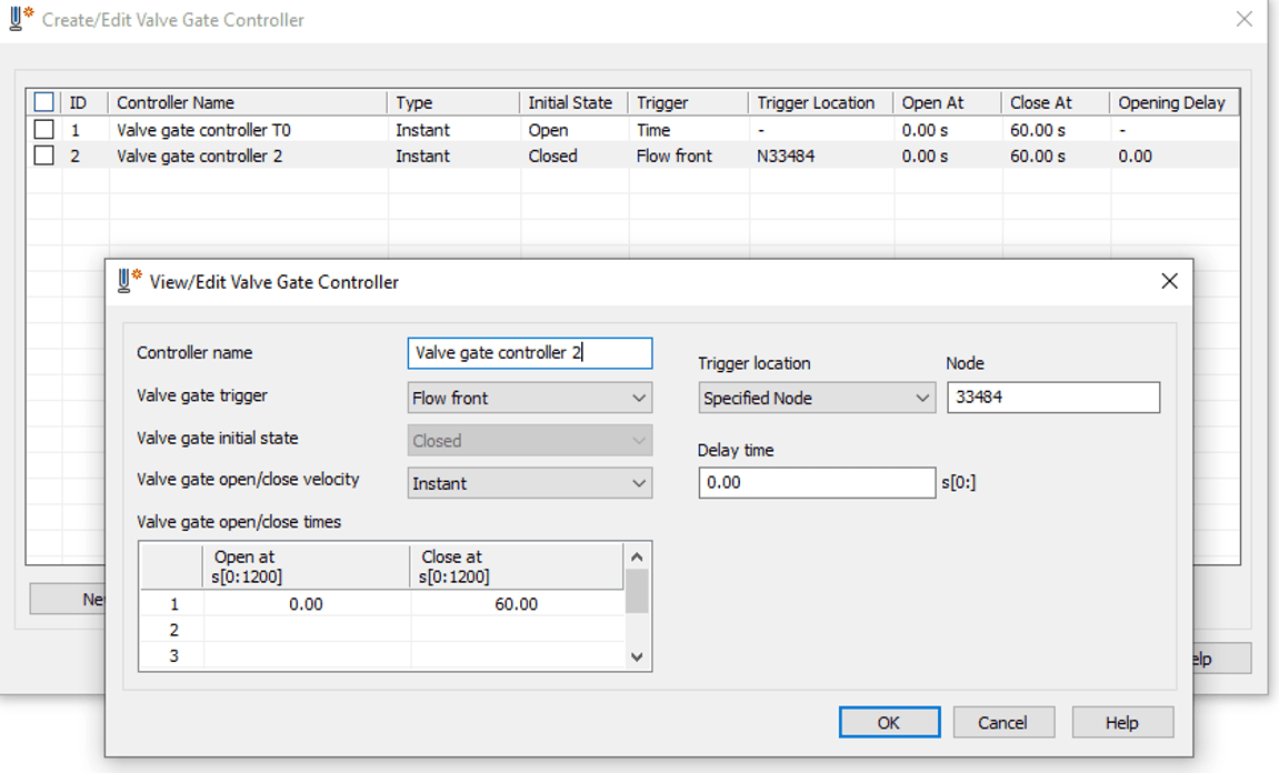
Valve Pin Control

Hot runner manufacturers have now developed controllers to

Read More

Can Gate Location Really affect Part Warpage?

By Bozilla
August 17, 2021

Based on part geometry, gate location(s) will determine how the polymer fills the cavity  If the cavity doesn’t fill in a balanced/uniform fashion, the internal stresses will be anisotropic- meaning non-uniform properties  So it is important to place a gate in a location such that the polymer flowfront fills the cavity at a uniform rate and reaches the end of the cavity at all locations, including weld line locations, simultaneously

With simple part geometry, identifying an ideal gate location may be possible by using experience and examining the part  However, with more complex geometry and gating limitations (cooling line interference, ejector pin interference, slides, etc), it is nearly impossible to determine the appropriate gate location(s) without using FEA(flow simulation)  Not only can FEA(flow simulation) produce actual deflection results(warpage), it can also provide data that is a precursor to warpage-such as volumetric shrinkage and frozen-in stress which is typically due to a response from forcing the material into the cavity while the material is trying to freeze

gate location and part warpage courtesy of sciencedirectcom

Gate location(s) will determine polymer orientation  Based on that location, it will ultimately determine polymer shrinkage  Also, different regions of the part will cool at different rates(regions of the cavity near the gate that were first to fill will cool before regions furthest from the gate)


Why is this important?  Because there are 3 major components that contribute to warpage:

 Polymer Orientation

Polymer Shrinkage

Cooling Effects


Shrinkage and orientation are both directly correlated to injection location(s) on a part as it relates to processing conditions  Warpage due to cooling effects is  based on the rate of how the polymer cools on one side of the cavity relative to the other side Non-uniform cooling through the thickness will create warpage

Because gate location(s) directly correlates to the contributors of warpage, gate location is therefore extremely important in the tool creation process and ultimately the quality of the part

The injection molding professionals at Bozilla Corporation have over 20 years of experience assisting OEM’s, Tier 1 & Tier 2 suppliers, and Tool Shops to create quality parts that meet timing and goals

wwwBozillaCorpcom


About the author

Chris Czeczuga President Bozilla Corporation

Chris Czeczuga is a Plastics Engineer, Injection molding expert, Military Veteran and the President of Bozilla Corporation He has proven success with many OEM’s Tier

Read More

Failure Diagnosis-Product & Process

By Bozilla
August 12, 2021

Bozilla Corporation’s core business is performing CAE analyses, specifically mold flow analyses, on products to optimize both design and process Our procedures and standards set a benchmark to create the highest degree of part quality with the least amount of difficulty and waste

Because many companies have not used FEA, they are turning to the injection molding specialists at Bozilla Corp with issues relating to part failure or processing problems Fortunately, we are solving many of them with Failure Diagnosis

What exactly is Failure Diagnosis?

Failure Diagnosis is the process of identifying why a product or process isn’t performing properly

The injection molding professionals at Bozilla Corporation have cultivated and executed proven techniques to execute this vital task and resolve our customers’ concerns on all levels

This type of diagnosis requires calculated procedures and thorough knowledge in:

✔ CAE Analysis

✔ Root Cause Analysis

✔ Experience with similar products/issues

✔ Indepth knowledge of polymers

If you are experiencing problems with a product in the field or with its process, we will implement our procedures to assist in solving these issues

 Some examples may include:

➤ Start up times for a tool are taking longer than expected, the process is difficult to stabilize, or the start up time on the same tool varies from machine to machine

➤ The process has variation and too many bad parts are being produced

➤ The parts seem to be fine but are failing in the field which causes customer dissatisfaction and more work/costs for you

As an added bonus, the Failure Diagnosis procedures can further lean your process and potentially save you money

Bozilla Corporation has worked extensively with companies to resolve their injection molding performance issues Contact us today and find out how we can help diagnosis any issues you may be having with your injection molding product and/or process and get you back on track!


wwwBozillaCorpcom

We Know Injection Molding! Plastics Engineering, Consulting, Optimization, Failure Diagnosis, Training

About the author

Chris Czeczuga is a Plastics Engineer, Injection molding expert, Military Veteran and the President of Bozilla Corporation He has proven success with many OEM’s Tier 1’s, Tier 2’s, Tool Shops, Molding shops, Part Designers, Processors and Fortune 500 companies throughout the injection molding industry A graduate from UMass Lowell, he is Expert Certified with Autodesk, has 20 years of field experience, intimate knowledge of injection molding part, tool and feed system design Bozilla Corporation’s success is built on providing the highest level of injection

Read More

Actual Injection Molded Part differs from Analytical Prediction

By Bozilla
July 28, 2021

In this discussion, we will explore a part that was injection molded and scanned for deflection Interestingly, the actual deflection did not match that of the analyzed part Unfortunately, this can sometimes happen and when it does, it is the responsibility of the software expert to investigate why the predicted analysis results are not matching the floor results This can be a challenging task

In the engineering world, it is common to hear the phrase ‘garbage in equals garbage out’ In other words that phrase means that all inputs plugged into any set of calculations will directly influence the outcome of those calculations When it comes to FEA, having correct input data is especially critical since technical software can only be as good as what is entered into each specific section But what steps should be taken if you have ensured that the analysis is set up correctly yet, the analytical results do not match the results on the floor? In the sample study below, we will take a closer look
For this study, we will look at a part that we will call the ‘console’:

Console Fill Console DeflectionConsole


We will compare the analytical inputs to the inputs used on the floor Then, we will explore how the analytical results compare to those on the floor

In preparation for any analysis, the user must take the necessary precautions to ensure that the inputs in the mold filling software are as accurate as possible

Part model

1) Is the part model prepared so that it meets or exceeds the standards that the software supplier recommends?

Yes, the part was modeled as a 3D model and exceeds the recommended criteria

Feed system design

2) Does the feed system match the final design of the finished product?

Yes, it was designed per the specifications provided by the tool shop

Material data

3) Is the material data in the analysis the same as what is being used on the floor?

Yes

   Is the material card comprehensive ie, is it fully characterized?

Yes

Process inputs

4) Do the process inputs in the software match the floor inputs?

Yes, see the Table 1 Below

analytical process setting vs floor process setting


Once the inputs have been confirmed as optimal and correct, we inspect the results and compare them

First, we examine the filling pattern to see if it is predicted correctly
To determine the correlation of flow patterns between Moldflow and

Read More

Finite Element Analysis(FEA) – On Every Tool?

By Bozilla
March 3, 2021

Finite Element Analysis (FEA) has been available to the injection molding industry since approximately 1978 when Moldflow pty Ltd produced the first simulation software to be used to optimize all phases of design and production processes for injection molded plastic parts

Over the years, FEA has proven to be a successful, cost-saving optimization method used for injection molded tool manufacturing


injection molding trouble shooting

Prior to FEA, a typical method used to refine product and process was to cut tool steel and design a feed system based on experience with older, comparable tools This method is also known as the trial and error method

This type of “guessing” process has cost manufacturers thousands of dollars in re-tooling and time delays that could have been prevented if they had first utilized FEA to troubleshoot the product and process

The question remains, “Should FEA be used for every tool?”  The answer is YES! Whether it is a new tool replacing an old tool running the same part, a New Tool being built for a new part, or a new mold for an existing part, FEA can positively refine both the quality of mold and the process

FEA is a gift to plastics manufacturers in that it provides an inside look at both the product and process before any steel is cut or altered  The refinement of product and process allows the manufacturer to perfect their part and save both time and money by limiting or preventing future rework

Contact Bozilla Corporation to assist you in achieving a successful part based on your budget and timing goals for your next project  We will provide you with detailed project data empowering you to make the most informed decisions to create a high quality mold

Do you remember the cost of your last mold?  If the answer is “yes”, do you really want to pay for it again because of rework/redesign?  

The plastic injection molding experts at Bozilla Corporation have over 20 years of experience with Autodesk Moldflow software, feed system design and field experience We provide the highest degree of professionalism, knowledge and quality to every project  Contact Bozilla Corporation Today and Let’s get started!

Read More

A Deeper Understanding Of Conformal Cooling For Injection Molds

By Bozilla
November 22, 2019

Conformal cooling has become the latest trend in the injection molding industry   As it compares to traditional gun-drilled cooling lines, it appears to be better, but is that always the case?  We will discuss the comparisons and application of both traditional cooling versus conformal cooling as it applies to heat removal of the polymer/part

When designing cooling for injection molds, several factors must be understood with regards to the properties of the tool steel such as the type of steel and its corresponding properties ie  thermal conductivity, thermal diffusivity, specific heat capacity and density   Those same properties must be considered for the coolant along with Reynolds number and flow rate

Thermal conductivity:

A measure of a materials ability to conduct heat as shown below:

Thermal Conductivity

Thermal diffusivity:

The thermal conductivity divided by the density and specific heat capacity (at constant pressure) as shown below:

Thermal diffusivity

In order to take advantage of these properties, certain guidelines should be considered such as the spacing between adjacent cooling circuits, thickness or cross section of the circuits and the spacing between cooling circuits and the cavity  The flow rate must be sufficient enough such that the coolant is turbulent (Reynolds number above 8000) in all regions of the circuits in order to have maximum heat removal

Conventional Cooling (gun-drilling):

Gun drilled cooling channels are straight holes cut through the tool steel  Because these are straight holes, it limits the regions in which holes can be cut such as in any action within the tool or small or difficult regions near the cavity of the tool  Implements can be used such as heat pipes (thermal pins), bubblers, baffles and small circuits and high heat-transfer materials  However, there are still regions within the tool that are difficult to implement cooling and these regions are typically accepted  They can cause issues within the mold such as parts sticking or controlling cycle time

Gun drilled cooling channels are very adequate when sized and spaced correctly  Basic guidelines will take advantage of the properties of both the coolant and the cooling channels:

  • The spacing of the cooling channel from center-line to center-line (pitch) should be no more than 3 times the diameter (3D)
  • The distance from the cooling channel to the cavity surfaces should be no more than 15 times the diameter (15D)

If these simple guidelines are maintained, there will be adequate

Read More